POWER MIRROR CONTROL SYSTEM TERMINALS OF ECU

-
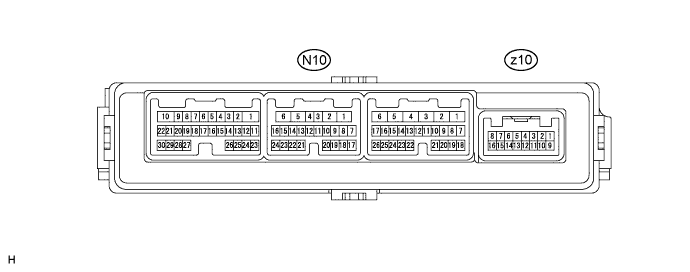
CHECK FRONT DOOR ECU LH
-
Disconnect the N10 and z10 ECU connectors.
-
Measure the voltage and resistance according to the value(s) in the table below.
Terminal No. (Symbols) Wiring Color Terminal Description Condition Specified Condition N10-1 (GND) - Body ground W-B - Body ground Ground Always Below 1 Ω N10-11 (CPUB) - N10-1 (GND) B*1 - W-B
R*2 - W-B
Battery (ECU power source) Always 11 to 14 V N10-3 (SIG) - N10-1 (GND) L*1 - W-B
V*2 - W-B
Ignition power supply Power switch OFF Below 1 V Power switch ON (IG) 11 to 14 V N10-6 (BDR) - N10-1 (GND) BE - W-B Battery (ECU power source) Always 11 to 14 V z10-12 (HTR-) - z10-4 (HTR+) W - B Mirror heater output and ground 25°C (77°F) 3.6 to 4.8 Ω Tech Tips
-
*1: for LHD
-
*2: for RHD
If the result is not as specified, there may be a malfunction on the wire harness side.
-
-
Reconnect the N10 and z10 ECU connectors.
-
Measure the voltage according to the value(s) in the table below.
Terminal No. (Symbols) Wiring Color Terminal Description Condition Specified Condition z10-3 (MR+) - N10-1 (GND) L - W-B Mirror retract motor output (retracting) Mirror retract switch ON (Outer rear view mirror LH is retracting) 11 to 14 V z10-11 (MR-) - N10-1 (GND) G - W-B Mirror retract motor output (returning) Mirror retract switch OFF (Outer rear view mirror LH is returning) 11 to 14 V z10-10 (DM+R) - N10-1 (GND)*1
z10-10 (PM+R) - N10-1 (GND)*2
R - W-B Mirror motor output Mirror master switch L, Mirror control switch OFF Below 1 V Mirror master switch L, Mirror control switch UP or LEFT Below 1 V Mirror master switch L, Mirror control switch DOWN or RIGHT 11 to 14 V z10-9 (DMHR) - N10-1 (GND)*1
z10-9 (PMHR) - N10-1 (GND)*2
BR - W-B Mirror motor output Mirror master switch L, Mirror control switch OFF Below 1 V Mirror master switch L, Mirror control switch RIGHT Below 1 V Mirror master switch L, Mirror control switch LEFT 11 to 14 V z10-1 (DMVR) - N10-1 (GND)*1
z10-1 (PMVR) - N10-1 (GND)*2
V - W-B Mirror motor output Mirror master switch L, Mirror control switch OFF Below 1 V Mirror master switch L, Mirror control switch DOWN Below 1 V Mirror master switch L, Mirror control switch UP 11 to 14 V z10-4 (HTR+) - N10-1 (GND) B - W-B Mirror heater output Rear defogger switch ON 11 to 14 V Rear defogger switch OFF Below 1 V z10-6 (VSSR) - z10-14 (DE2)*1
z10-6 (VSSR) - z10-14 (PE2)*2
Y-B - GR Vertical direction position signal Mirror master switch R or L
Mirror control switch UP or DOWN
Voltage fluctuates between 0 and 5 V z10-13 (HSSR) - z10-14 (DE2)*1
z10-13 (HSSR) - z10-14 (PE2)*2
P - GR Horizontal direction position signal Mirror master switch RIGHT or LEFT
Mirror control switch RIGHT or LEFT
Voltage fluctuates between 0 and 5 V z10-5 (DVC) - z10-14 (DE2)*1
z10-5 (PVC) - z10-14 (PE2)*2
R-W - GR Power source for mirror position sensor Power switch OFF during sleep mode Below 1 V Power switch ON (IG) 3.5 to 5.5 V N10-21 (ECI+) - N10-22 (ECI-) R - L EC mirror signal Electrochromic mirror system is operating 1.05 to 1.35 V Electrochromic mirror system is not operating Below 1 V z10-7 (EC+) - z10-15 (EC-) B-G - B-R EC mirror signal Electrochromic mirror system is operating 1.05 to 1.35 V Electrochromic mirror system is not operating Below 1 V Tech Tips
-
*1: for LHD
-
*2: for RHD
If the result is not as specified, the ECU may have a malfunction.
-
-
-
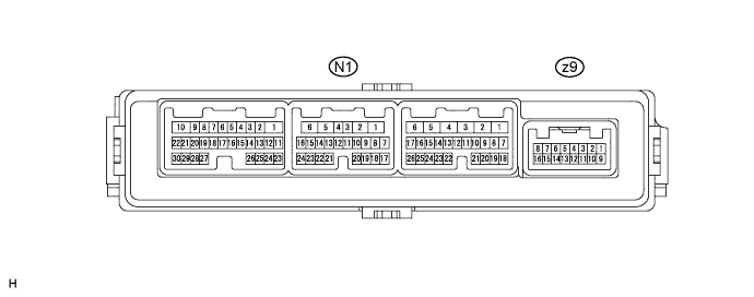
CHECK FRONT DOOR ECU RH
-
Disconnect the N1 and z9 ECU connectors.
-
Measure the voltage and resistance according to the value(s) in the table below.
Terminal No. (Symbols) Wiring Color Terminal Description Condition Specified Condition N1-1 (GND) - Body ground W-B - Body ground Ground Always Below 1 Ω N1-11 (CPUB) - N1-1 (GND) R*1 - W-B
B*2 - W-B
Battery (ECU power source) Always 11 to 14 V N1-3 (SIG) - N1-1 (GND) V*1 - W-B
L*2 - W-B
Ignition power supply Power switch OFF Below 1 V Power switch ON (IG) 11 to 14 V N1-6 (BDR) - N1-1 (GND) BE - W-B Battery (ECU power source) Always 11 to 14 V z9-12 (HTR-) - z9-4 (HTR+) W - B Mirror heater output and ground 25°C (77°F) 3.6 to 4.8 Ω Tech Tips
-
*1: for LHD
-
*2: for RHD
If the result is not as specified, there may be a malfunction on the wire harness side.
-
-
Reconnect the N1 and z9 ECU connectors.
-
Measure the voltage according to the value(s) in the table below.
Terminal No. (Symbols) Wiring Color Terminal Description Condition Specified Condition z9-3 (MR+) - N1-1 (GND) L - W-B Mirror retract motor output (retracting) Mirror retract switch ON (Outer rear view mirror RH is retracting) 11 to 14 V z9-11 (MR-) - N1-1 (GND) G - W-B Mirror retract motor output (returning) Mirror retract switch OFF (Outer rear view mirror RH is returning) 11 to 14 V z9-10 (PM+R) - N1-1 (GND)*1
z9-10 (DM+R) - N1-1 (GND)*2
R - W-B Mirror motor output Mirror master switch R, Mirror control switch OFF Below 1 V Mirror master switch R, Mirror control switch UP or LEFT Below 1 V Mirror master switch R, Mirror control switch DOWN or RIGHT 11 to 14 V z9-9 (PMHR) - N1-1 (GND)*1
z9-9 (DMHR) - N1-1 (GND)*2
BR - W-B Mirror motor output Mirror master switch R, Mirror control switch OFF Below 1 V Mirror master switch R, Mirror control switch RIGHT Below 1 V Mirror master switch R, Mirror control switch LEFT 11 to 14 V z9-1 (PMVR) - N1-1 (GND)*1
z9-1 (DMVR) - N1-1 (GND)*2
V - W-B Mirror motor output Mirror master switch R, Mirror control switch OFF Below 1 V Mirror master switch R, Mirror control switch DOWN Below 1 V Mirror master switch R, Mirror control switch UP 11 to 14 V z9-4 (HTR+) - N1-1 (GND) B - W-B Mirror heater output Rear defogger switch ON 11 to 14 V Rear defogger switch OFF Below 1 V z9-6 (VSSR) - z9-14 (PE2)*1
z9-6 (VSSR) - z9-14 (DE2)*2
Y-B - GR Vertical direction position signal Mirror master switch R or L
Mirror control switch UP or DOWN
Voltage fluctuates between 0 and 5 V z9-13 (HSSR) - z9-14 (PE2)*1
z9-13 (HSSR) - z9-14 (DE2)*2
P - GR Horizontal direction position signal Mirror master switch R or L
Mirror control switch RIGHT or LEFT
Voltage fluctuates between 0 and 5 V z9-5 (PVC) - z9-14 (PE2)*1
z9-5 (DVC) - z9-14 (DE2)*2
R-W - GR Power source for mirror position sensor Power switch ON (ACC) or OFF during sleep mode Below 1 V Power switch ON (IG) 3.5 to 5.5 V N1-21 (ECI+) - N1-22 (ECI-) R - L EC mirror signal Electrochromic mirror system is operating 1.05 to 1.35 V Electrochromic mirror system is not operating Below 1 V z9-7 (EC+) - z9-15 (EC-) B-G - B-R EC mirror signal Electrochromic mirror system is operating 1.05 to 1.35 V Electrochromic mirror system is not operating Below 1 V Tech Tips
-
*1: for LHD
-
*2: for RHD
If the result is not as specified, the ECU may have a malfunction.
-
-
-
CHECK OUTER MIRROR SWITCH ASSEMBLY

-
Disconnect the L6 switch connector.
-
Measure the voltage and resistance according to the value(s) in the table below.
Terminal No. (Symbols) Wiring Color Terminal Description Condition Specified Condition L6-1 (E) - Body ground W-B - Body ground Ground Always Below 1Ω L6-12 (B) - L6-1 (E) B - W-B Battery (ECU power source) Always 11 to 14 V L6-11 (IG) - L6-1 (E) G - W-B Ignition power supply Power switch OFF Below 1 V Power switch ON (IG) 11 to 14 V If the result is not as specified, there may be a malfunction on the wire harness side.
-