OUTER REAR VIEW MIRROR REMOVAL

Tech Tips
-
Use the same procedures for the LH side and RH side.
-
The procedures listed below are for the LH side.
-
PRECAUTION
Note
After turning the power switch off, waiting time may be required before disconnecting the cable from the auxiliary battery terminal. Therefore, make sure to read the disconnecting the cable from the auxiliary battery terminal notice before proceeding with work Click here.
-
REMOVE LUGGAGE COMPARTMENT MAT SUB-ASSEMBLY (w/ Spare Tire)

-
REMOVE DECK BOARD ASSEMBLY (w/o Spare Tire)

-
REMOVE DECK TRIM SIDE BOARD LH (w/o Spare Tire)
-

Detach the 2 clips and remove the deck trim side board LH.
-
-
REMOVE BATTERY SERVICE HOLE COVER LH
-

Text in Illustration *A for Standard *B for Ottoman *1 Fastening Tape Detach the clip, fastening tape and remove the battery service hole cover LH.
-
-
DISCONNECT CABLE FROM AUXILIARY BATTERY NEGATIVE TERMINAL
Note
When disconnecting the cable, some systems need to be initialized after the cable is reconnected Click here.
-
REMOVE FRONT DOOR INSIDE HANDLE BEZEL PLUG LH
-
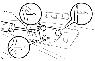
Text in Illustration *1 Protective Tape Using a screwdriver, detach the 3 claws and remove the front door inside handle bezel plug LH.
Tech Tips
Tape the screwdriver tip before use.
-
-
REMOVE POWER WINDOW REGULATOR MASTER SWITCH ASSEMBLY WITH FRONT DOOR ARMREST BASE PANEL
-
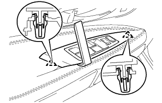
Using a moulding remover D, detach the 2 clips.
-
Disconnect the connector and remove the power window regulator master switch assembly with front door armrest base panel.
Tech Tips
Tape the screwdriver tip before use.
-
-
REMOVE FRONT DOOR TRIM BOARD SUB-ASSEMBLY LH
-
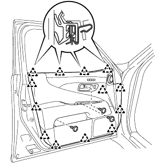
Remove the 3 screws.
-
Detach the 13 clips and remove the front door trim board sub-assembly LH.
-
Disconnect the connector.
-
Disconnect the 2 cables from the inside handle.
-
-
REMOVE DOOR FRAME GARNISH LH
-
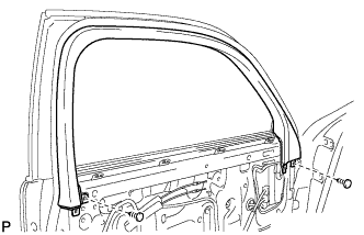
Remove the 2 clips and door frame garnish LH.
-
-
REMOVE MULTIPLEX NETWORK FRONT DOOR ECU LH
-
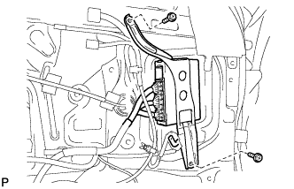
Remove the 2 screws and front multiplex network door ECU LH.
-
Disconnect the 3 connectors.
-
-
REMOVE FRONT DOOR NO. 2 SERVICE HOLE COVER LH
-
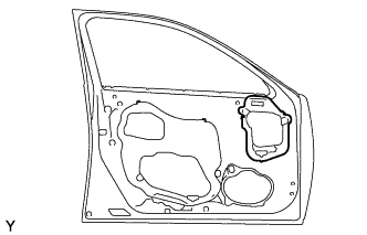
Remove the front door No. 2 service hole cover LH.
Tech Tips
Remove the remaining tape on the door.
-
-
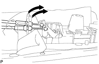
REMOVE OUTER REAR VIEW MIRROR ASSEMBLY LH
-
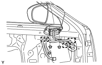
Detach the 3 clamps.
-
Remove the 3 nuts and outer rear view mirror assembly LH.
-