INNER REAR VIEW MIRROR INSTALLATION

Tech Tips
-
Use the same procedure for RHD and LHD vehicles.
-
The procedure listed below is for LHD vehicles.
-
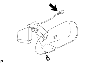
INSTALL INNER REAR VIEW MIRROR ASSEMBLY (w/ Automatic High Beam System, Adaptive High Beam System)
Note
-
Do not touch the camera lens (built into the inner rear view mirror assembly) with a bare hand.
-
Do not allow anything to adhere to the camera lens (built into the inner rear view mirror assembly).
-
Do not apply strong impacts to the inner rear view mirror assembly.
-
Do not allow any liquid to get on the inner rear view mirror assembly.
-
Using a T20 "TORX" socket wrench, install the inner rear view mirror with the screw.
- Torque:
- 1.8 N*m { 18 kgf*cm, 16 in.*lbf }
-
Connect the connector.
-
-
INSTALL INNER REAR VIEW MIRROR ASSEMBLY (w/o Automatic High Beam System, Adaptive High Beam System)
-
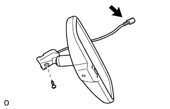
Using a T20 "TORX" socket wrench, install the inner rear view mirror with the screw.
- Torque:
- 1.8 N*m { 18 kgf*cm, 16 in.*lbf }
-
Connect the connector.
-
-
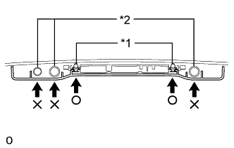
INSTALL RAIN SENSOR COVER (w/ Lane Keeping Assist System)
Note
-
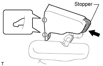
When installing the rain sensor cover, do not apply force to the object recognition camera areas labeled "X".
-
When installing the rain sensor cover, apply force to the areas labeled "○" to attach the clips.
Text in Illustration *1 Clip *2 Camera
-
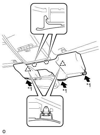
While being careful not to apply force to the camera areas, attach the 2 claws and 2 clips to install the rain sensor cover.
-
Push the stopper as shown in the illustration to fix the cover in place.
-
-
INSTALL RAIN SENSOR COVER (w/o Lane Keeping Assist System)
-
Attach the 2 claws to install the rain sensor cover.
-
Push the stopper as shown in the illustration to fix the cover in place.
-
-
INSTALL MAP LIGHT ASSEMBLY
-
Connect the connectors.
-
Attach the 2 clips to install the map light assembly.
-
Install the 2 screws.
-
Attach the 2 claws and 2 covers.
-
-
CONNECT CABLE TO AUXILIARY BATTERY NEGATIVE TERMINAL
Note
When disconnecting the cable, some systems need to be initialized after the cable is reconnected Click here.
-
INSTALL BATTERY SERVICE HOLE COVER LH
-

Text in Illustration *A for Standard *B for Ottoman Attach the battery service hole cover LH with the clip and fastening tape.
-
-
INSTALL DECK TRIM SIDE BOARD LH (w/o Spare Tire)
-

Attach the 2 clips to install the deck trim side board LH.
-
-
INSTALL DECK BOARD ASSEMBLY (w/o Spare Tire)

-
INSTALL LUGGAGE COMPARTMENT MAT SUB-ASSEMBLY (w/ Spare Tire)

-
ADJUST ADAPTIVE HIGH BEAM CAMERA BEAM AXIS (w/ Automatic High Beam System, Adaptive High Beam System)