BACK WINDOW GLASS INSTALLATION

-
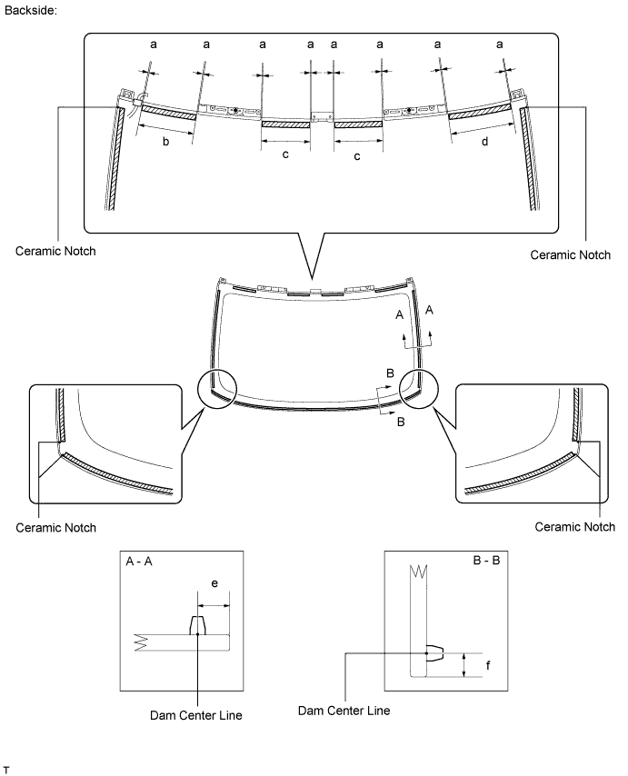
INSTALL BACK WINDOW GLASS DAM
-
Apply Primer G to the installation part of the window glass dam.
Note
-
Allow the primer to dry for 3 minutes or more.
-
Throw away any leftover primer.
-
Do not apply too much primer.
-
-
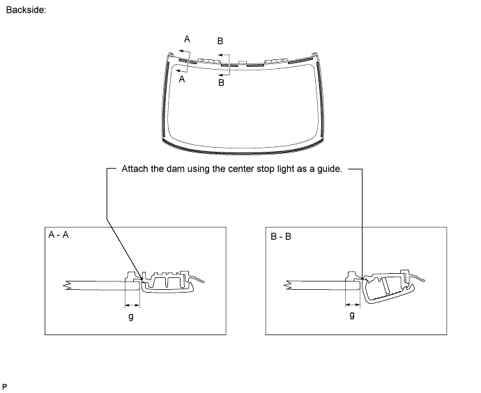
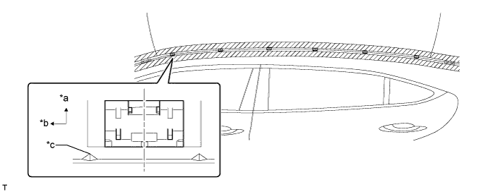
Remove the peeling paper from the adhesive part of the dam. Install the dam (adhesive side) to the glass (Primer G area) as shown in the illustration.
Tech Tips
Attach the dam using the center stop light as a guide.
Standard Area Specified Condition a 1.0 mm (0.0393 in.) or less b 159.0 mm (6.25 in.) c 146.0 mm (5.74 in.) d 192.0 mm (7.55 in.) e 9.5 mm (0.377 in.) f 7.5 mm (0.295 in.) g (Reference) 8.0 mm (0.315 in.)
-
-
INSTALL BACK WINDOW GLASS
-
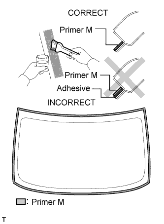
Using a brush or sponge, apply Primer M to the exposed part of the vehicle body.
Note
-
Allow the primer to dry for 3 minutes or more.
-
Do not apply primer to the adhesive.
-
Throw away any leftover primer.
-
Do not apply too much primer.
-
-
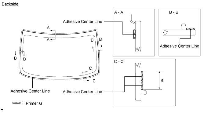
Using a brush or sponge, apply Primer G to the contact surface of the back window glass.
Standard Area Specified Condition a 19.0 mm (0.748 in.) Tech Tips
If primer is applied to an area that is not specified, wipe off the primer with a non-residue solvent before it dries.
Note
-
Allow the primer to dry for 3 minutes or more.
-
Throw away any leftover primer.
-
Do not apply too much primer.
-
-
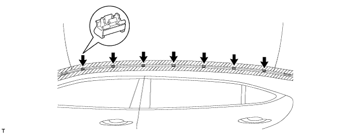
Apply adhesive to the back window glass.
Adhesive Toyota Genuine Windshield Glass Adhesive or equivalent
-
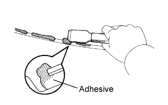
Cut off the tip of the cartridge nozzle as shown in the illustration below.
Tech Tips
After cutting off the tip, use all adhesive within the time frame written in the table below.
Usage time frame Temperature Usage Time Frame 35°C (95°F) 15 minutes 20°C (68°F) 1 hour 40 minutes 5°C (41°F) 8 hours -
Load the sealer gun with the cartridge.
-
Apply adhesive to the back window glass as shown in the illustration.
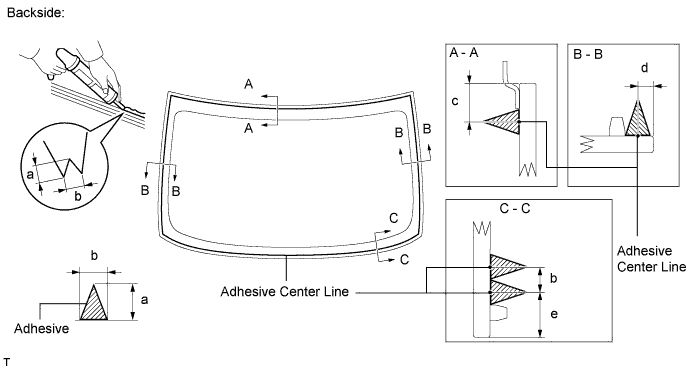
Standard Area Specified Condition a 12.0 mm (0.472 in.) b 8.0 mm (0.315 in.) c 12.1 mm (0.476 in.) d 3.0 mm (0.118 in.) e 14 mm (0.551 in.)
-
-
Install the back window glass to the vehicle body.
-
Hold the back window glass securely in place with tape or equivalent until the adhesive has hardened.
Note
-
Allow the primer coating to dry for 3 minutes or more.
-
Check that the clips are attached to the vehicle body correctly.
-
Check the clearance between the vehicle body and glass.
-
-
Lightly press the front surface of the back window glass to ensure that the back window glass is securely fit to the vehicle body.
-
Using a scraper, remove any excess or protruding adhesive.
Tech Tips
Apply adhesive onto the glass rim.
Note
Do not drive the vehicle within the time written in the table below.
Minimum time Temperature Minimum time prior to driving vehicle 35°C (95°F) 1 hour 30 minutes 20°C (68°F) 5 hours 5°C (41°F) 24 hours -
Install the defogger wire with the nut and 2 clamps.
-
Connect the 2 connectors.
-
-
-
CHECK FOR LEAK AND REPAIR
-
Conduct a leak test after the adhesive has completely hardened.
-
Seal any leaks with auto glass sealer.
-
-
INSTALL CENTER STOP LIGHT ASSEMBLY
-
Attach the 2 claws to install the center stop light assembly.
-
Install the 2 screws.
-
Connect the harness and connector.
-
-
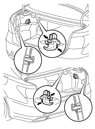
INSTALL CENTER STOP LIGHT CLIP
-
Turn the 2 center stop light clips 90° and install them.
-
-
INSTALL CENTER STOP LIGHT COVER
-
Attach the 4 claws to install the center stop light cover.
-
-
INSTALL CENTER NO. 2 STOP LIGHT COVER
-
Attach the 4 claws to install the No. 2 center stop light cover.
-
-
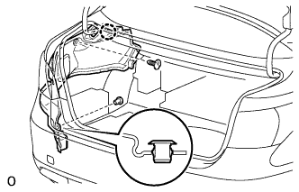
INSTALL LUGGAGE COMPARTMENT DOOR HINGE COVER LH
-
Clean the vehicle body surface.
-
Using a heat light, heat the vehicle body surface.
-
Remove the double-sided tape from the vehicle body.
-
Wipe off any tape adhesive residue with cleaner.
-
-
Install the moulding.
-
Using a heat light, heat the vehicle body and moulding.
-
Remove the peeling paper from the face of the moulding.
Tech Tips
After removing the peeling paper, keep the exposed adhesive free from foreign matter.
-
-
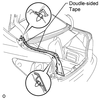
Attach the 2 clips to install the a new moulding.
-
-
INSTALL LUGGAGE COMPARTMENT DOOR HINGE COVER RH
Tech Tips
Use the same procedures described for the LH side.
-
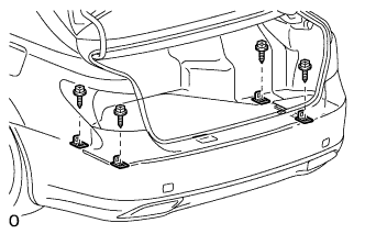
INSTALL REAR COMBINATION LIGHT ASSEMBLY LH
-
Move the rear combination light assembly LH in the direction of the arrow in the illustration and attach the clip, 2 claws and 2 guides to install the rear combination light assembly LH.
-
Install the 3 nuts.
- Torque:
- 4.5 N*m { 46 kgf*cm, 40 in.*lbf }
-
Connect the connector.
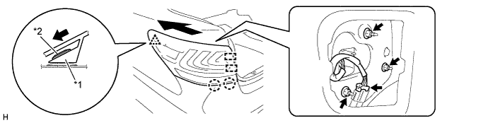
Text in Illustration *1 Rear Combination Light Assembly LH *2 Clip
-
-
INSTALL REAR COMBINATION LIGHT ASSEMBLY RH
Tech Tips
Use the same procedure described for the LH side.
-
INSTALL LUGGAGE COMPARTMENT TRIM COVER ASSEMBLY LH
-
Install the luggage compartment trim cover assembly LH with the claw and 2 clips.
-
-
INSTALL LUGGAGE COMPARTMENT TRIM COVER ASSEMBLY RH
-
Install the luggage compartment trim cover assembly RH with the claw and 2 clips.
-
-
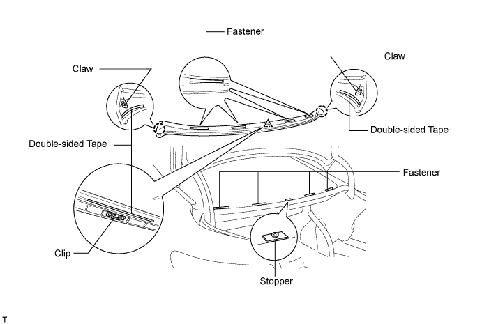
INSTALL LOWER BACK WINDOW MOULDING OUTSIDE
-
Clean the vehicle body surface.
-
Using a heat light, heat the vehicle body surface.
-
Remove the double-sided tape from the vehicle body.
-
Wipe off any tape adhesive residue with cleaner.
-
-
Install the moulding.
-
Using a heat light, heat the moulding.
-
Remove the peeling paper from the face of the moulding.
Tech Tips
After removing the peeling paper, keep the exposed adhesive free from foreign matter.
-
-
Attach the clip on the center of the moulding. Use the stoppers (left and right setting stoppers) on the bottom edge of the back window glass to determine the moulding's orientation Then attach the 2 claws and 4 fasteners to install the a new moulding.
Tech Tips
As the stoppers on the bottom edge of the glass are only for determining the moulding's position, they do not attach to the moulding.
-
-
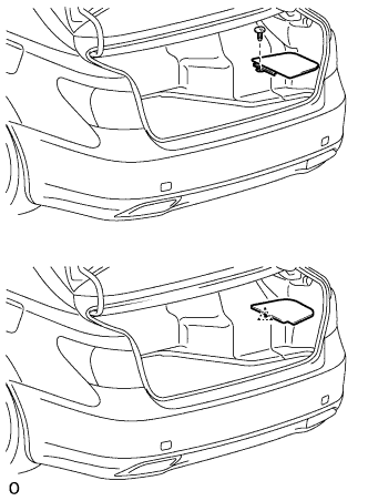
INSTALL REAR FLOOR FINISH PLATE
-
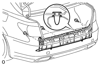
Attach the 4 clips to install the rear floor finish plate.
-
Install the 3 clips.
-
-
INSTALL FRONT LUGGAGE COMPARTMENT TRIM COVER
-
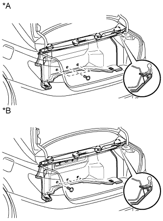
Text in Illustration *A w/o Rear Cooler *B w/ Rear Cooler Attach the 4 claws to install the front luggage compartment trim cover.
-
Install the 3 clips.
-
-
INSTALL NO. 1 LUGGAGE COMPARTMENT LIGHT ASSEMBLY
-
Connect the connector.
-
Attach the 2 claws to Install the No. 1 luggage compartment light assembly.
-
-
INSTALL NO. 1 COOLER COVER
-
Attach the 5 clips to install the No. 1 cooler cover.
-
-
INSTALL DECK TRIM SIDE BOARD RH
-
Text in Illustration *A w/ Spare Tire *B w/o Spare Tire w/ Spare Tire:
-
Install the deck trim side board RH with the clip.
-
-
w/o Spare Tire:
-
Attach the clip to install the deck trim side board RH.
-
-
-
INSTALL ROPE HOOK ASSEMBLY
-
Install the 4 rope hook assemblies with the 4 bolts.
-
-
INSTALL ROPE HOOK
-
Install the 4 rope hooks.
-
-
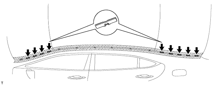
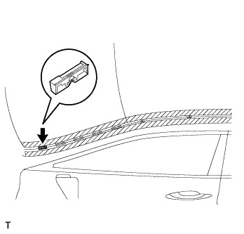
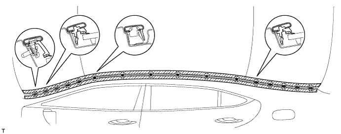
INSTALL NO. 1 ROOF DRIP SIDE FINISH MOULDING CLIP
Tech Tips
Perform the following procedure if replacing the No. 1 roof drip side finish moulding clip.
Note
Remove the double-sided tape remaining where the clips will be installed on the body and clean the body with a non-residue type solvent.
-
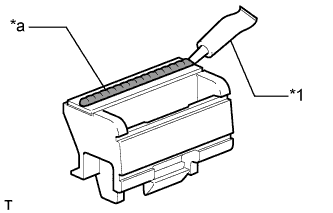
Text in Illustration *1 Adhesive *a 2 to 3 mm Bead of Adhesive Apply a 2 to 3 mm (0.07 to 0.11 in.) bead of adhesive (3M DP-105 or equivalent) to new No. 1 roof drip side finish moulding clips.
Tech Tips
Adhesive strength (tensile strength): 13.7 MPa (140 kgf/cm2, 1991 psi) or more {when the temperature is 23°C (73°F)}
-
for Standard Body:
Press and install the 6 No. 1 roof drip side finish moulding clips.
-
for Long Body:
Press and install the 7 No. 1 roof drip side finish moulding clips.
-
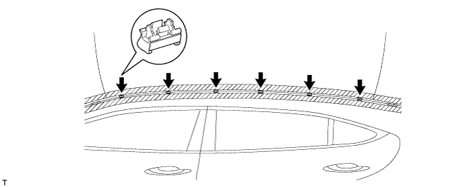
Install the clips to the positions on the roof panel shown in the illustration. Determine the locations and firmly press and install the No. 1 roof drip side finish moulding clips after lightly applying adhesive (3M DP-105 or equivalent).
-
Install the center roof drip side finish moulding when 40 minutes or more have elapsed after pressing and installing the No. 1 roof drip side finish moulding clips.
Tech Tips
-
Initial hardening time: 40 minutes
-
Complete hardening time: 48 hours
Text in Illustration *a Outside *b Front *c Location - -
-
-
-
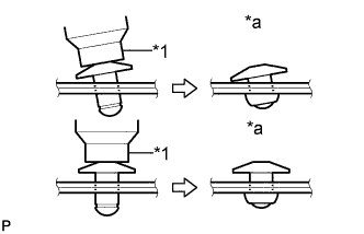
INSTALL NO. 3 WINDSHIELD OUTSIDE MOULDING CLIP
Tech Tips
Perform the following procedure if replacing the No. 3 outside windshield moulding clip.
-
Using an air riveter or hand riveter with a nose piece, install the 10 new rivets.
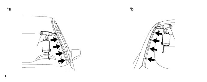
Text in Illustration *a Front Side *b Rear Side Tech Tips
If the rivet cannot be cut, pull it once and cut it.
Note
-
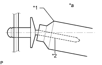
Do not pry the rivet with the riveter, as this will cause damage to the riveter and mandrel.
Text in Illustration *1 Riveter *2 Mandrel *a INCORRECT -
Confirm that the rivets are seated properly against the moulding.
Text in Illustration *1 Riveter *a INCORRECT -
Do not tilt the riveter when installing the rivet to the moulding.
-
Do not leave any space between the rivet head and moulding.
-
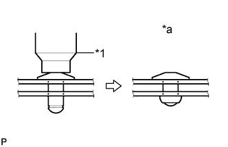
Do not leave any space between the moulding and door frame. Firmly hold together the 2 items while installing the rivet.
Text in Illustration *1 Riveter *a INCORRECT
-
-
-
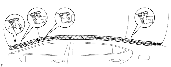
INSTALL NO. 2 ROOF DRIP SIDE FINISH MOULDING CLIP
Tech Tips
Perform the following procedure if replacing the No. 2 roof drip side finish moulding clips.
-
Install the 9 No. 2 roof drip side finish moulding clips.
-
-
INSTALL NO. 2 WINDSHIELD OUTSIDE MOULDING CLIP
Tech Tips
Perform the following procedure if replacing the No. 2 outside windshield moulding clip.
-
Install the No. 2 outside windshield moulding clip.
-
-
INSTALL NO. 1 WINDSHIELD OUTSIDE MOULDING CLIP
Tech Tips
Use the same procedures described for the No. 2 windshield outside moulding clip.
-
INSTALL CENTER ROOF DRIP SIDE FINISH MOULDING LH
-
for Standard Body:
Attach the 16 clips to install the center roof drip side finish moulding LH.
-
for Long Body:
Attach the 17 clips to install the center roof drip side finish moulding.
-
Remove the protective tape from the edges of the center roof drip side finish moulding.
-
-
INSTALL CENTER ROOF DRIP SIDE FINISH MOULDING RH
Tech Tips
Use the same procedures described for the LH side.
-
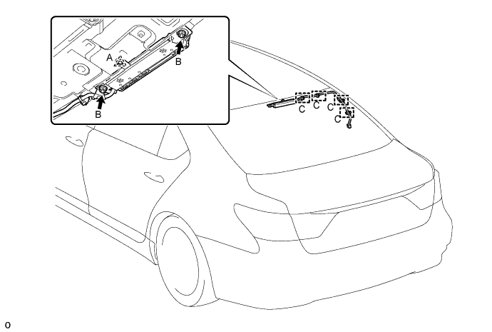
INSTALL AMPLIFIER ANTENNA ASSEMBLY
-
Use non-residue solvent to clean the area on the glass where the antenna will be installed.
Note
Do not use non-residue solvent to clean the antenna's contact points. Doing so may cause improper contact between the antenna and glass.
-
Install the antenna with the 2 nuts labeled B.
- Torque:
- 14 N*m { 143 kgf*cm, 10 ft.*lbf }
Note
-
Just before installing the antenna to the glass, remove the protective cover of the antenna's contact points.
-
When removing the protective cover of the antenna's contact points, make sure the cover does not touch the contact points.
-
Never touch the contact points after removing the protective cover.
Tech Tips
-
Remove the clip if it is damaged.
-
The clip is used when the vehicle is assembled at the factory and is not needed for the reinstallation.
-
Attach the 4 clamps labeled C.
-
Connect each connector.
-
-
INSTALL ROOF HEADLINING ASSEMBLY
-
Return the roof headlining to its original position.
For Standard Body, refer to the following procedures Click here.
For Long Body, refer to the following procedures Click here.
-
-
INSTALL ASSIST GRIP SUB-ASSEMBLY
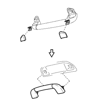
Tech Tips
Use the same procedure for all the assist grips.
-
Assemble the assist grip sub-assembly, 2 clips and 2 covers as shown in the illustration.
-
Attach the 2 clips to install the assist grip sub-assembly.
-
-
INSTALL ROOF SIDE REGISTER BEZEL LH (w/ Rear Cooler)
-
Attach the claw to install the roof side register bezel LH.
-
Install the screw.
-
-
INSTALL ROOF SIDE REGISTER BEZEL RH (w/ Rear Cooler)
Tech Tips
Use the same procedure described for the LH side.
-
INSTALL COAT HOOK
Tech Tips
Use the same procedure to install the hook on the other side.
-
Install the coat hook with the screw.
-
-
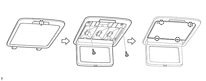
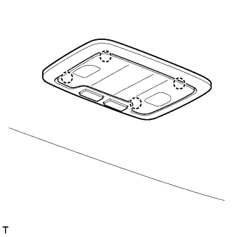
INSTALL REAR VANITY LIGHT ASSEMBLY
Tech Tips
Use the same procedure to install the vanity light assembly on the other side.
-
Connect the connector.
-
Attach the claw to install the vanity light assembly.
-
Install the 2 screws.
-
Attach the 4 claws to install the lens.
-
-
INSTALL SPOT LIGHT ASSEMBLY (w/ Rear Seat Entertainment System)
-
Connect the connector.
-
Attach the 4 claws to install the spot light assembly.
-
-
INSTALL ROOF CONSOLE BOX ASSEMBLY (w/ Rear Seat Entertainment System)
-
w/o Sliding Roof:
-
Connect the connector.
-
Attach the 2 hooks, 6 clips and 2 claws to install the roof console box assembly.
-
Install the 2 screws.
-
-
w/ Sliding Roof:
-
Connect the connector.
-
Attach the 2 hooks and 6 clips to install the roof console box assembly.
-
Install the 2 screws.
-
-
-
INSTALL NO. 2 PACKAGE TRAY TRIM PANEL ASSEMBLY
-
Attach the 5 claws and 3 clips to install the No. 2 package tray trim panel assembly.
-
-
INSTALL PACKAGE TRAY TRIM PANEL ASSEMBLY
-
Connect the solar sensor connector.
-
except 4-Passenger with Ottoman:
Pass the 3 rear seat belt floor anchors through the package tray trim panel assembly.
-
for 4-Passenger with Ottoman:
Pass the 2 rear seat belt floor anchors through the package tray trim panel assembly.
-
Insert the rear part of the package tray trim panel assembly into the rear sunshade assembly.
-
Attach the 2 clips to install the package tray trim panel assembly.
-
except 4-Passenger with Ottoman:
Attach the 4 claws to install the 3 belt guides.
-
for 4-Passenger with Ottoman:
Attach the 4 claws to install the 2 belt guides.
-
-
INSTALL INNER ROOF SIDE GARNISH LH
Text in Illustration *1 Clip A
-
Install a new clip A to the inner roof side garnish LH.
-
Attach the 2 claws and 5 clips to install the inner roof side garnish LH.
-
-
INSTALL INNER ROOF SIDE GARNISH RH
Tech Tips
Use the same procedure described for the LH side.
-
INSTALL REAR SEAT SIDE GARNISH LH
-
Attach the 6 claws to install the rear seat side garnish LH.
-
-
INSTALL REAR SEAT SIDE GARNISH RH
Tech Tips
Use the same procedure described for the LH side.
-
INSTALL REAR DOOR SCUFF PLATE LH
-
for Standard Body:
-
for Long Body:
-
-
INSTALL REAR DOOR SCUFF PLATE RH
-
for Standard Body:
-
for Long Body:
-
-
INSTALL REAR SEAT ASSEMBLY
-
for Power Seat:
-
for Ottoman:
-
for Fixed Seat Type:
-
-
CONNECT CABLE TO AUXILIARY BATTERY NEGATIVE TERMINAL
Note
When disconnecting the cable, some systems need to be initialized after the cable is reconnected Click here.
-
INSTALL BATTERY SERVICE HOLE COVER LH
-

Text in Illustration *A for Standard *B for Ottoman Attach the battery service hole cover LH with the clip and fastening tape.
-
-
INSTALL DECK TRIM SIDE BOARD LH (w/o Spare Tire)
-

Attach the 2 clips to install the deck trim side board LH.
-
-
INSTALL DECK BOARD ASSEMBLY (w/o Spare Tire)

-
INSTALL LUGGAGE COMPARTMENT MAT SUB-ASSEMBLY (w/ Spare Tire)
