WINDSHIELD GLASS INSTALLATION

Tech Tips
A bolt without a torque specification is shown in the standard bolt chart Click here.
-
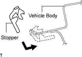
INSTALL NO. 1 WINDSHIELD GLASS STOPPER
-
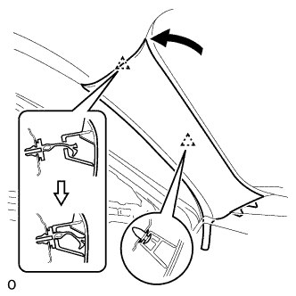
Install 2 new stoppers to the vehicle body as shown in the illustration.
-
-
INSTALL NO. 2 WINDSHIELD GLASS STOPPER
-
Apply Primer G to the glass where the stopper will be installed.
Note
-
Allow the primer to dry for 3 minutes or more.
-
Throw away any leftover primer.
-
Do not apply too much primer.
-
-
Install 2 new stoppers onto the glass as shown in the illustration.
-
-
INSTALL UPPER WINDSHIELD OUTSIDE MOULDING
-
Using a brush or sponge, coat the contact surface of the glass and moulding with Primer G.
Note
-
Allow the primer coating to dry for 3 minutes or more.
-
Do not coat the adhesive with Primer G.
-
Throw away any leftover primer.
-
-
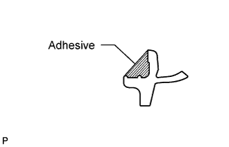
Apply adhesive to the moulding as shown in the illustration.
Adhesive Toyota Genuine Windshield Glass Adhesive or equivalent Tech Tips
Use all adhesive within the time written in the table below.
Usage timeframe Temperature Usage Timeframe 35°C (95°F) 15 minutes 20°C (68°F) 1 hour 40 minutes 5°C (41°F) 8 hours -
Install the windshield outside moulding, as shown in the illustration.
Note
Make sure the glass and moulding are flush.
-

Remove any unnecessary adhesive before it hardens.
Note
Make sure that no adhesive remains on the moulding and glass. Do Not Leave Any
-
-
INSTALL WINDSHIELD GLASS RETAINER
-
Apply Primer G to the glass where the retainer will be installed.
Note
-
Allow the primer to dry for 3 minutes or more.
-
Throw away any leftover primer.
-
Do not apply too much primer.
-
-
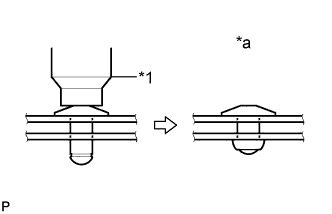
Install 2 new retainers onto the glass as shown in the illustration.
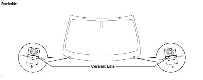
Standard Area Specified Condition a 30.0 mm (1.18 in.)
-
-
INSTALL WINDSHIELD GLASS ADHESIVE DAM
-
Apply Primer G to the glass where the glass adhesive dams will be installed.
Note
-
Allow the primer to dry for 3 minutes or more.
-
Throw away any leftover primer.
-
Do not apply too much primer.
-
-
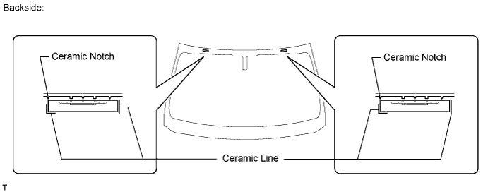
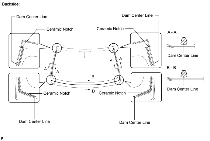
Remove the peeling paper from the adhesive part of the dam. Install the dam (adhesive side) to the glass (Primer G area), but exclude the area above the notches on the upper part of the glass.
-
-
INSTALL WINDSHIELD GLASS SEAL
-
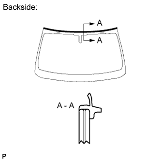
Remove the peeling paper from the windshield glass seal. Install the seal to the glass.
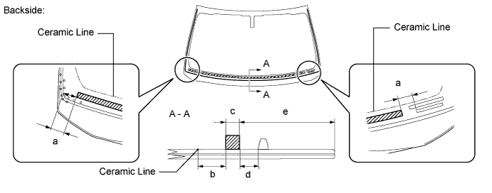
Standard Area Specified Condition a 30.0 mm (1.18 in.) b 20.0 mm (0.787 in.) c 10.0 mm (0.394 in.) d 13.0 mm (0.512 in.) e 88.7 mm (3.49 in.)
-
-
INSTALL WINDSHIELD GLASS
-
Position the glass.
-
Using suction cups, place the glass in the correct position.
-
Check that the entire contact surface of the glass rim is perfectly even.
-
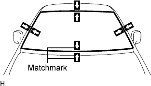
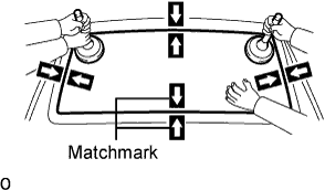
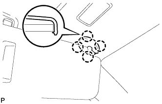
Place matchmarks on the glass and vehicle body on the locations indicated in the illustration.
Tech Tips
-
Placing matchmarks is only necessary when installing new glass. If it is the reused glass, matchmarks should already be present.
-
When reusing the glass, check and correct the matchmark positions.
Note
Check that the stoppers are attached to the vehicle body correctly.
-
-
Using suction cups, remove the glass.
-
-
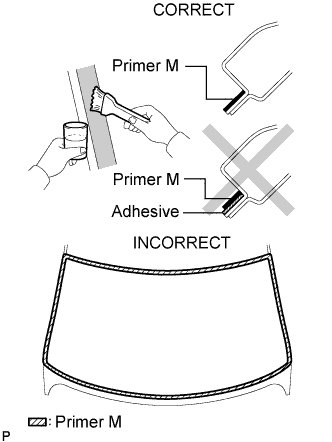
Using a brush, apply Primer M to the exposed part of the vehicle body.
Note
-
Allow the primer to dry for 3 minutes or more.
-
Do not apply primer to the adhesive.
-
Throw away any leftover primer.
-
Do not apply too much primer.
-
-
Using a brush or sponge, apply Primer G to the contact surface of the glass.
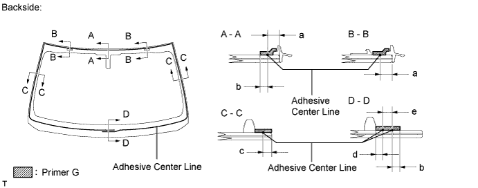
Standard Area Specified Condition a 6.5 mm (0.258 in.) b 7.0 mm (0.276 in.) c 3.0 mm (0.118 in.) d 4.0 mm (0.157 in.) e 8.0 mm (0.315 in.) Tech Tips
If the primer is applied to an area that is not specified, apply non-residue solvent to a clean cloth and wipe off the excess primer before it dries.
Note
-
Allow the primer to dry for 3 minutes or more.
-
Throw away any leftover primer.
-
Do not apply too much primer.
-
-
Apply adhesive to the glass.
Adhesive Toyota Genuine Windshield Glass Adhesive or equivalent
-
Cut off the tip of the cartridge nozzle as shown in the illustration.
Tech Tips
After cutting off the tip, use all adhesive within the time written in the table below.
Usage timeframe Temperature Usage Timeframe 35°C (95°F) 15 minutes 20°C (68°F) 1 hour 40 minutes 5°C (41°F) 8 hours -
Load the sealer gun with the cartridge.
-
Apply adhesive to the glass as shown in the illustration.
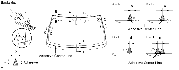
Standard Area Specified Condition a 12.0 mm (0.472 in.) b 8.0 mm (0.315 in.) c 6.5 mm (0.258 in.) d 3.0 mm (0.118 in.)
-
-
Install the glass to the vehicle body.
-
Using suction cups, position the glass so that the matchmarks are aligned. Press it in gently along the rim.
-
Lightly press the outer surface of the glass to ensure that it is securely fit to the vehicle body.
Note
-
Check that the stoppers are attached to the vehicle body correctly.
-
Check that the vehicle body and glass have a small gap between them.
-
-
Hold the glass in place securely with protective tape or equivalent until the adhesive hardens.
Note
Do not drive the vehicle for the amount of time written in the table below.
Minimum time Temperature Minimum time prior to driving vehicle 35°C (95°F) 1 hour 30 minutes 20°C (68°F) 5 hours 5°C (41°F) 24 hours
-
-
w/ Windshield Deicer System:
Connect the windshield deicer connector.
-
-
CHECK FOR LEAK AND REPAIR
-
Conduct a leak test after the adhesive has completely hardened.
-
Seal any leaks with auto glass sealer.
-
-
INSTALL ROOF HEADLINING ASSEMBLY
-
Return the roof headlining to its original position.
For Standard Body, refer to the following procedures Click here.
For Long Body, refer to the following procedures Click here.
-
-
INSTALL RAIN SENSOR TAPE
-
If reusing the rain sensor:
Install new rain sensor tape.
-
Remove the used rain sensor tape from the windshield glass or rain sensor.
-
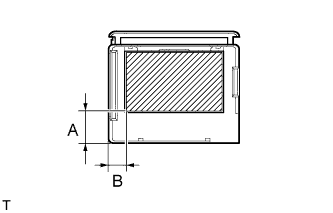
Apply new rain sensor tape on the rain sensor lens surface in the area indicated by the hatched area.
Note
-
Keep the tape's exposed adhesive free from dust and fingerprints.
-
Apply the tape exactly according to the specifications below.
Specification Area Measurement A 15.0 mm (0.591 in.) B 8.0 mm (0.315 in.)
-
-
-
-
INSTALL RAIN SENSOR
Note
-
Make sure the adhesive between the bracket and windshield glass is normal.
-
If there is any residue left from the rain sensor tape on the windshield, remove it.
-
Clean the glass surface with cloth or similar material.
-
Make sure there are no air bubbles between the rain sensor and windshield.
-
Peel the peeling paper from the rain sensor tape.
-
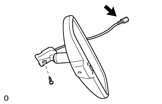
Securely attach the rain sensor to the bracket.
-
Push in the stopper.
-
Connect the connector.
-
-
INSTALL OBJECT RECOGNITION CAMERA (w/ Driver Monitor Camera)
Note
-
Do not touch the camera lens when removing or installing the camera.
-
Do not use a camera which has been dropped or subjected to an impact.
-
If the camera is not installed securely, the system may not operate properly. Therefore, be sure to install the camera securely.
-
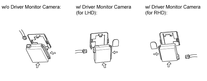
Push the bracket to attach the clip.
-
Allow the wire harness to hang down.
-
Do not press the sensor, as it may become deformed.
-
Temporarily install the object recognition camera with the clip.
-
Install the 3 bolts in alphabetical order.
- Torque:
- 9.0 N*m { 92 kgf*cm, 80 in.*lbf }
-
Attach the claw to connect the connector clamp.
-
Attach the 2 wire harness clamps.
-
Connect the 3 connectors.
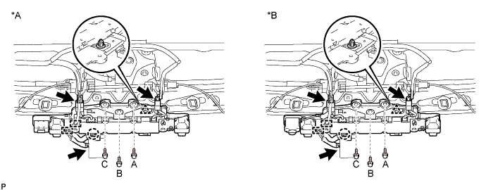
Text in Illustration *A w/o Night View System *B w/ Night View System -
Return the roof headlining to its original position.
-
-
INSTALL INNER REAR VIEW MIRROR ASSEMBLY (w/ Automatic High Beam System, Adaptive High Beam System)
Note
-
Do not touch the camera lens (built into the inner rear view mirror assembly) with a bare hand.
-
Do not allow anything to adhere to the camera lens (built into the inner rear view mirror assembly).
-
Do not apply strong impacts to the inner rear view mirror assembly.
-
Do not allow any liquid to get on the inner rear view mirror assembly.
-
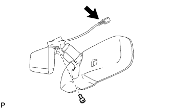
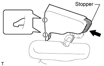
Using a T20 "TORX" socket wrench, install the inner rear view mirror with the screw.
- Torque:
- 1.8 N*m { 18 kgf*cm, 16 in.*lbf }
-
Connect the connector.
-
-
INSTALL INNER REAR VIEW MIRROR ASSEMBLY (w/o Automatic High Beam System, Adaptive High Beam System)
-
Using a T20 "TORX" socket wrench, install the inner rear view mirror with the screw.
- Torque:
- 1.8 N*m { 18 kgf*cm, 16 in.*lbf }
-
Connect the connector.
-
-
INSTALL RAIN SENSOR COVER (w/o Driver Monitor Camera)
-
Attach the 2 claws to install the rain sensor cover.
-
Push the stopper as shown in the illustration to fix the cover in place.
-
-
INSTALL RAIN SENSOR COVER (w/ Driver Monitor Camera)
Note
-
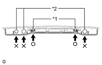
When installing the rain sensor cover, do not apply force to the object recognition camera areas labeled "X".
-
When installing the rain sensor cover, apply force to the areas labeled "○" to attach the clips.
Text in Illustration *1 Clip *2 Camera
-
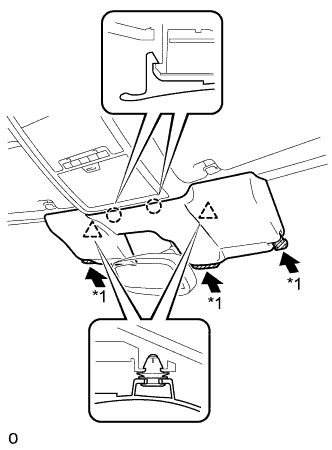
While being careful not to apply force to the camera areas, attach the 2 claws and 2 clips to install the rain sensor cover.
-
Push the stopper as shown in the illustration to fix the cover in place.
-
-
INSTALL MAP LIGHT ASSEMBLY
-
Connect the connectors.
-
Attach the 2 clips to install the map light assembly.
-
Install the 2 screws.
-
Attach the 2 claws and 2 covers.
-
-
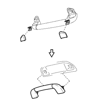
INSTALL ASSIST GRIP SUB-ASSEMBLY
Tech Tips
Use the same procedure for all the assist grips.
-
Assemble the assist grip sub-assembly, 2 clips and 2 covers as shown in the illustration.
-
Attach the 2 clips to install the assist grip sub-assembly.
-
-
INSTALL VISOR HOLDER
Tech Tips
Use the same procedure to install the visor holder on the other side.
-
Attach the 2 claws to install the visor holder.
-
Push in the visor holder and turn it approximately 45° as shown in the illustration.
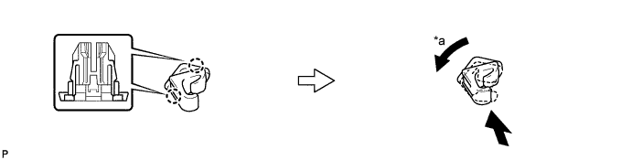
Text in Illustration *a 45° - -
-
-
INSTALL VISOR ASSEMBLY LH
-
Install the visor assembly with the 2 screws.
-
-
INSTALL VISOR ASSEMBLY RH
Tech Tips
Use the same procedure described for the LH side.
-
INSTALL VISOR BRACKET COVER
Tech Tips
Use the same procedure to install the cover on the other side.
-
Attach the 4 claws to install the visor bracket cover.
-
-
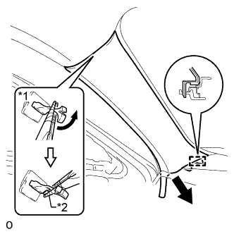
INSTALL FRONT PILLAR GARNISH LH
-
Attach the guide.
-
Turn the end of the front pillar garnish clip 90° with needle-nose pliers and install it to the front pillar garnish LH.
Tech Tips
Tape the tips of the needle-nose pliers before use.
Text in Illustration *1 Front Pillar Garnish Clip *2 Protective Tape -
Attach the 2 clips to install the front pillar garnish LH.
Note
After installing the front pillar garnish LH, make sure that the lip of the front door opening trim weatherstrip LH is not pinched.
-
-
INSTALL FRONT PILLAR GARNISH RH
Tech Tips
Use the same procedure described for the LH side.
-
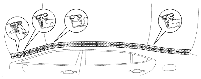
INSTALL NO. 1 ROOF DRIP SIDE FINISH MOULDING CLIP
Tech Tips
Perform the following procedure if replacing the No. 1 roof drip side finish moulding clip.
Note
Remove the double-sided tape remaining where the clips will be installed on the body and clean the body with a non-residue type solvent.
-
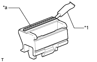
Text in Illustration *1 Adhesive *a 2 to 3 mm Bead of Adhesive Apply a 2 to 3 mm (0.07 to 0.11 in.) bead of adhesive (3M DP-105 or equivalent) to new No. 1 roof drip side finish moulding clips.
Tech Tips
Adhesive strength (tensile strength): 13.7 MPa (140 kgf/cm2, 1991 psi) or more {when the temperature is 23°C (73°F)}
-
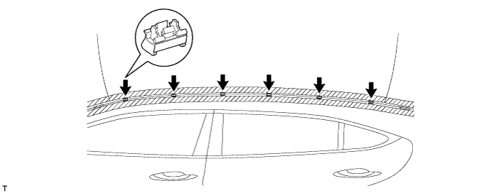
for Standard Body:
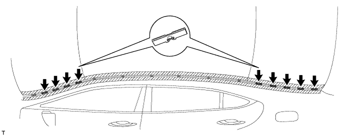
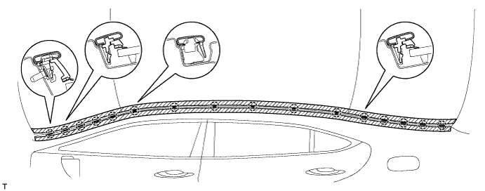
Press and install the 6 No. 1 roof drip side finish moulding clips.
-
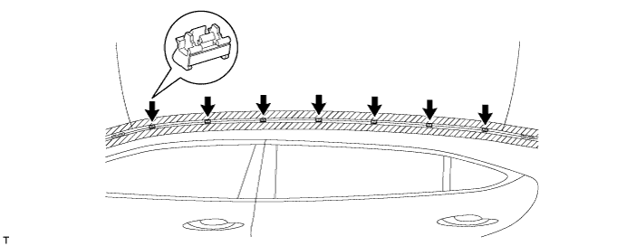
for Long Body:
Press and install the 7 No. 1 roof drip side finish moulding clips.
-
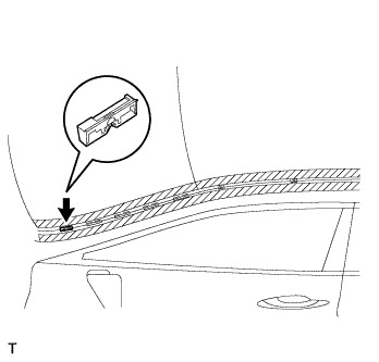
Install the clips to the positions on the roof panel shown in the illustration. Determine the locations and firmly press and install the No. 1 roof drip side finish moulding clips after lightly applying adhesive (3M DP-105 or equivalent).
-
Install the center roof drip side finish moulding when 40 minutes or more have elapsed after pressing and installing the No. 1 roof drip side finish moulding clips.
Tech Tips
-
Initial hardening time: 40 minutes
-
Complete hardening time: 48 hours
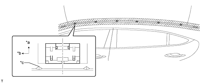
Text in Illustration *a Outside *b Front *c Location - -
-
-
-
INSTALL NO. 3 WINDSHIELD OUTSIDE MOULDING CLIP
Tech Tips
Perform the following procedure if replacing the No. 3 outside windshield moulding clip.
-
Using an air riveter or hand riveter with a nose piece, install the 10 new rivets.
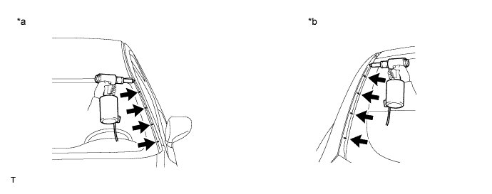
Text in Illustration *a Front Side *b Rear Side Tech Tips
If the rivet cannot be cut, pull it once and cut it.
Note
-
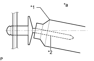
Do not pry the rivet with the riveter, as this will cause damage to the riveter and mandrel.
Text in Illustration *1 Riveter *2 Mandrel *a INCORRECT -
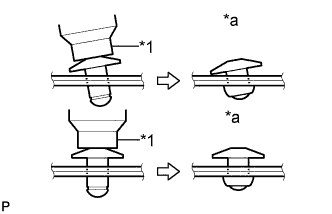
Confirm that the rivets are seated properly against the moulding.
Text in Illustration *1 Riveter *a INCORRECT -
Do not tilt the riveter when installing the rivet to the moulding.
-
Do not leave any space between the rivet head and moulding.
-
Do not leave any space between the moulding and door frame. Firmly hold together the 2 items while installing the rivet.
Text in Illustration *1 Riveter *a INCORRECT
-
-
-
INSTALL NO. 2 ROOF DRIP SIDE FINISH MOULDING CLIP
Tech Tips
Perform the following procedure if replacing the No. 2 roof drip side finish moulding clips.
-
Install the 9 No. 2 roof drip side finish moulding clips.
-
-
INSTALL NO. 2 WINDSHIELD OUTSIDE MOULDING CLIP
Tech Tips
Perform the following procedure if replacing the No. 2 outside windshield moulding clip.
-
Install the No. 2 outside windshield moulding clip.
-
-
INSTALL NO. 1 WINDSHIELD OUTSIDE MOULDING CLIP
Tech Tips
Use the same procedures described for the No. 2 windshield outside moulding clip.
-
INSTALL CENTER ROOF DRIP SIDE FINISH MOULDING LH
-
for Standard Body:
Attach the 16 clips to install the center roof drip side finish moulding LH.
-
for Long Body:
Attach the 17 clips to install the center roof drip side finish moulding.
-
Remove the protective tape from the edges of the center roof drip side finish moulding.
-
-
INSTALL CENTER ROOF DRIP SIDE FINISH MOULDING RH
Tech Tips
Use the same procedures described for the LH side.
-
INSTALL COWL TOP VENTILATOR LOUVER SUB-ASSEMBLY
-
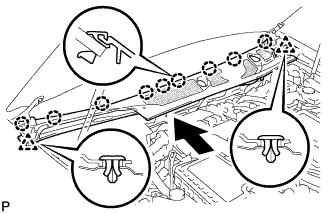
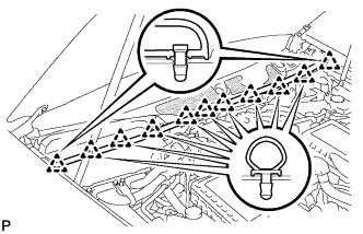
Push the ventilator louver in the direction indicated by the arrow in the illustration to attach the 9 claws and 2 clips and install the ventilator louver.
-
-
INSTALL COWL TOP VENTILATOR LOUVER PROTECTOR LH
-
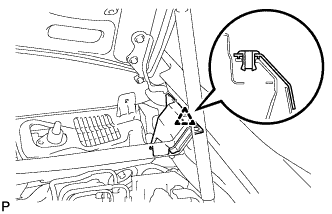
Attach the claw and guide to install the cowl top ventilator louver protector LH.
-
Attach the clip.
-
-
INSTALL COWL TOP VENTILATOR LOUVER RH (for LHD)
-
Install the cowl top ventilator louver RH with the 6 clips.
Note
Be sure to install the cowl top ventilator louver RH properly. If it is not installed properly, water may enter the engine room and cause malfunctions.
-
-
INSTALL COWL TOP VENTILATOR LOUVER LH (for RHD)
-
Install the cowl top ventilator louver RH with the 6 clips.
Note
Be sure to install the cowl top ventilator louver RH properly. If it is not installed properly, water may enter the engine room and cause malfunctions.
-
-
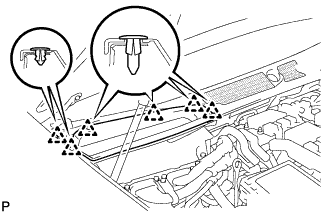
INSTALL HOOD TO COWL TOP SEAL
-
Attach the 11 clips to install the cowl top seal.
-
-
INSTALL FRONT FENDER TO COWL SIDE SEAL LH
-
Attach the claw and clip to install the front fender to cowl side seal LH.
-
-
INSTALL FRONT FENDER TO COWL SIDE SEAL RH
Tech Tips
Use the same procedures described for the LH side.
-
INSTALL FRONT WIPER ARM LH
-
Stop the wiper motor at the automatic stop position.
-
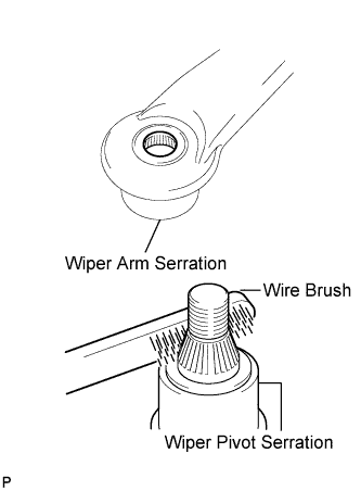
Clean the wiper arm serration with a round file or equivalent.
-
Clean the wiper pivot serration with a wire brush.
-
Install the wiper arm and blade with the nut. Make sure that the wiper arm and blade comes to the position shown in the illustration.
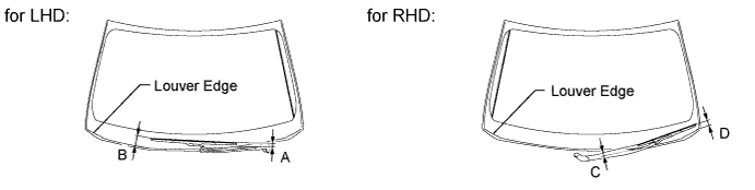
Standard measurement Position Specified Condition A 16.3 mm (0.646 in.) B 61.7 to 76.7 mm (2.43 to 3.02 in.) C 23.2 mm (0.913 in.) D 35.6 to 50.6 mm (1.40 to 1.99 in.) - Torque:
- 22 N*m { 224 kgf*cm, 16 ft.*lbf }
Tech Tips
Hold down the wiper arm hinge with your hand while tightening the nut.
-
-
INSTALL FRONT WIPER ARM RH
-
Stop the wiper motor at the automatic stop position.
-
Clean the wiper arm serration with a round file or equivalent.
-
Clean the wiper pivot serration with a wire brush.
-
Install the wiper arm and blade with the nut. Make sure that the wiper arm and blade comes to the position shown in the illustration.
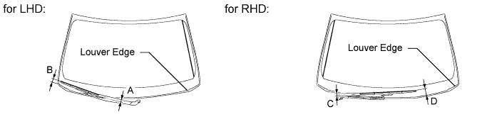
Standard measurement Position Specified Condition A 23.2 mm (0.913 in.) B 35.6 to 50.6 mm (1.40 to 1.99 in.) C 16.3 mm (0.646 in.) D 61.7 to 76.7 mm (2.43 to 3.02 in.) - Torque:
- 22 N*m { 224 kgf*cm, 16 ft.*lbf }
Tech Tips
Hold down the wiper arm hinge with your hand while tightening the nut.
-
Operate the front wipers while spraying washer fluid on the windshield glass. Make sure that the front wipers function properly and there is no interference with the vehicle body.
-
-
CONNECT CABLE TO AUXILIARY BATTERY NEGATIVE TERMINAL
Note
When disconnecting the cable, some systems need to be initialized after the cable is reconnected Click here.
-
INSTALL BATTERY SERVICE HOLE COVER LH
-

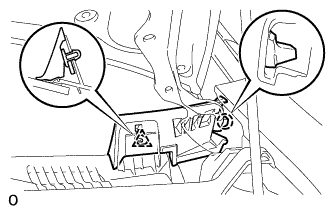
Text in Illustration *A for Standard *B for Ottoman Attach the battery service hole cover LH with the clip and fastening tape.
-
-
INSTALL DECK TRIM SIDE BOARD LH (w/o Spare Tire)
-

Attach the 2 clips to install the deck trim side board LH.
-
-
INSTALL DECK BOARD ASSEMBLY (w/o Spare Tire)

-
INSTALL LUGGAGE COMPARTMENT MAT SUB-ASSEMBLY (w/ Spare Tire)

-
ADJUST OBJECT RECOGNITION CAMERA
Note
-
Make sure there are no black and white patterned objects in front of the vehicle.
-
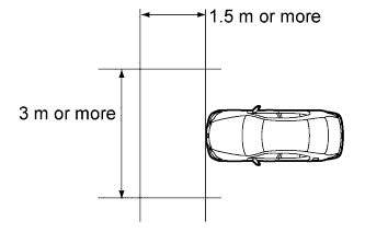
Perform the measurement in a place with no wind, and make sure there is a distance of 1.5 m (4.92 ft.) or more in front of the vehicle and that the surface is level with no obstacles.
-
Make sure that there is no wind when performing the measurement.
-
Check that there are no reflective materials in the surroundings or on the ground within a 3 m (9.84 ft.) or more x 3 m (9.84 ft.) or more area in front of the vehicle.
-
Perform the inspection in a bright area.
-
Beam axis learning preparation
-
Move the vehicle to a level surface.
-
Make sure the engine oil in the vehicle is at the specified amount.
-
Make sure the engine coolant in the vehicle is at the specified amount.
-
Make sure the fuel tank is full.
-
Make sure the spare tire is in the vehicle. (w/ Spare Tire)
-
Make sure the standard tools are in the vehicle.
-
Make sure nobody is in the vehicle.
-
Make sure no extra loads are in the vehicle.
-
Adjust the tire pressures to the specified pressure.
-
Clean the front glass.
-
If the lens of the object recognition camera sensor is dirty, apply a small amount of lens cleaner to a clean, soft cloth and clean the lens.
-
-
Perform height control sensor adjustment
-
Perform the height control sensor adjustment Click here.
Note
Perform this procedure as accurately as possible.
-
-
Perform the front wheel alignment adjustment
-
Perform the front wheel alignment adjustment Click here.
Note
Perform this procedure as accurately as possible.
-
-
Perform the rear wheel alignment adjustment
-
Perform the rear wheel alignment adjustment Click here.
Note
-
Perform this procedure as accurately as possible.
-
Press the height control switch and change the vehicle height to HIGH and return it to NORM. Then repeat.
-
-
-
Target sheet creation
-
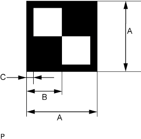
Print or copy the illustration below. Check that the dimensions are +/-5 mm (0.197 in.) of the ones in the table below.
Dimension Area Specification A 160 mm (6.30 in.) B 80 mm (3.15 in.) C 16 mm (0.630 in.) Note
-
Make sure that the black areas of the target sheets are not glossy.
-
Make sure that the borders of the black and white areas on the target sheets are straight, and are not warped or blurry.
If the print or copy's dimensions are not as specified, adjust settings and reprint or recopy so that the print or copy's dimensions are as specified.

-
-
-
Target sheet attachment
-
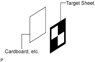
Place the prepared target sheet on a piece of cardboard of the same size with the black area on the top right, as shown in the illustration. Then use double-sided tape to fix the target sheet in place.
Note
Do not attach reflective tape, such as scotch tape, etc. to the target face as this may affect target recognition.
-
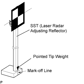
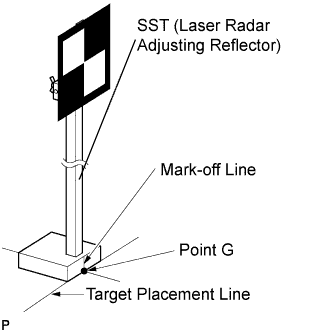
Hang a weight with a pointed tip from the center of the target sheet. Then, with double-sided tape, attach the target sheet to the reflector so that the weight aligns with the mark-off line of SST (laser radar adjusting reflector).
- SST
- 09870-60000 ( 09870-60010, 09870-60020 )
Note
-
Perform this procedure as accurately as possible.
-
Attach the target sheet so that it is horizontal with the ground.
-
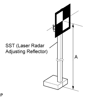
Move the reflector up and down to position the center of the target at the height shown in the illustration, and fix it in place.
Dimension A 1270 mm (4.17ft.) - SST
- 09870-60000 ( 09870-60010, 09870-60020 )
Note
Perform this procedure as accurately as possible.
-
-
Target placement point measurement
Note
-
Perform this procedure as accurately as possible.
-
Do not place reflective materials in the area behind the target.
-
Make sure there are no patterns on the wall behind the target.
-
Make sure the distance between the target and wall is within 3 m (9.84 ft.).
-
Do not place black and white patterned objects near the target.
-
Make sure the target's shadow is not on the wall, as the camera may have a recognition error.
-
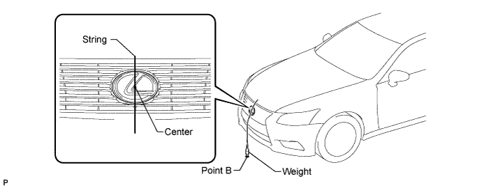
From the center of the front bumper (center of the emblem), hang a weight with a pointed tip, and mark point B on the ground.
-
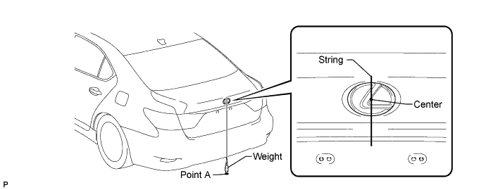
From the center of the rear bumper (center of the emblem), hang a weight with a pointed tip, and mark point A on the ground.
-
Using a piece of string that uses point A as a starting point and that passes through point B, make a straight line on the ground ahead of the vehicle 2 m (6.56 ft.) or more from point B.
Tech Tips
-
Make sure to secure the string (using tape, etc.) when it is taut.
-
Lightly flick the string with your fingers several times to confirm that the string is aligned above point B.
-
-
Mark point C at a position 340 mm (1.12 ft.) from point B.
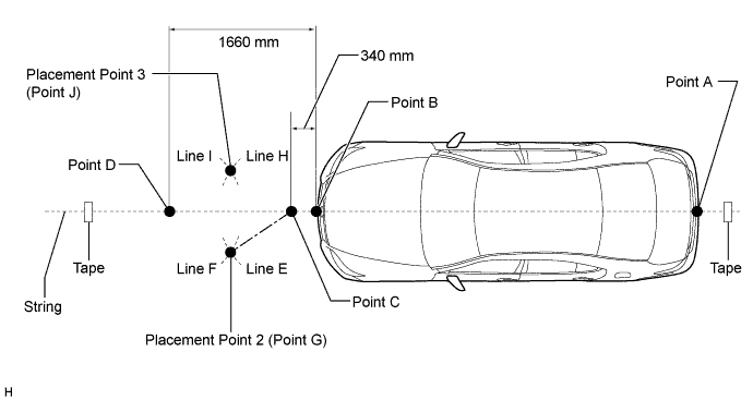
-
Mark point D at a position 1660 mm (5.44 ft.) from point B.
-
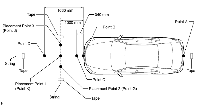
Using the string, mark line E at a position 1000 mm (3.28 ft.) from point C.
-
Using the string, mark line H at a position 1000 mm (3.28 ft.) from point C.
-
Using the string, mark line F at a position 1000 mm (3.28 ft.) from point D.
-
Using the string, mark line I at a position 1000 mm (3.28 ft.) from point D.
-
Mark point G at the point where line E and line F intersect (placement point 2).
-
Mark point J at the point where line H and line I intersect (placement point 3).
-
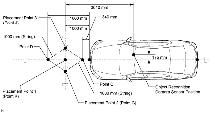
Secure a string that connects point G and point J to the ground (target placement line).
-
Mark point K at the intersection between the string connecting points C and D and the string connecting points G and J (placement point 1).
-
Confirm the distance measurements for points K, G, and J (placement points 1, 2, and 3) again.
-
-
Object recognition camera sensor height measurement
Note
-
Do not place black and white patterned objects near the target.
-
Face the vehicle toward a wall with no patterns, or make sure the background behind the target has no patterns.
-
Perform this procedure as accurately as possible.
-
Do not place reflective materials in the area behind the target.
-
Make sure there are no patterns on the wall behind the target.
-
Make sure the distance between the target and wall is within 3 m (9.84 ft.).
-
Make sure the target's shadow is not on the wall, as the camera may have a recognition error.
-
Measure the distance (X mm or in.) from the ground to point H for the front left wheel arch.
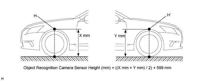
-
Measure the distance (Y mm or in.) from the ground to point H for the front right wheel arch.
-
The average of the 2 distances (X mm or in. Y mm or in.) plus 599 mm (23.6 in.) is the height of the object recognition camera sensor.
-
-
Memorize camera/target position
Note
-
Close all doors.
-
Perform the procedure with no one in the vehicle.
-
During the procedure, do not lean on the vehicle.
-
Illuminate the clearance lights.
-
Do not illuminate the headlights.
-
Connect the intelligent tester to the DLC3.
-
Turn the power switch ON (IG).*1
-
Turn the intelligent tester main switch ON.
-
Select "Auto" from the display screen and proceed to the next screen.
-
Select each option for the vehicle being adjusted from the display screen.
-
Select "Chassis" or "Body" from the display screen.
-
Select "Lane Keeping Assist" or "Pre-Crash 2" and then "Utility" from the display screen
-
Select "Camera/target position memory" from the display screen.
-
Follow the tester display, and select "Next".
-
Input the measured height of the object recognition camera sensor and the horizontal position of the camera "175 mm (6.89 in.)" into the input screen. Then press the "Next" button on the display screen.
-
Input "3010 mm (119 in.)" for the distance from the camera to the target and "1270 mm (50.0 in.)" for the height of the target into the input screen. Then press the "Next" button on the display screen.
Tech Tips
When the "Next" button is pressed, a 70 second countdown begins.
-
Press the "Exit" button to finish the camera/target position memory mode.
Note
If "Error Camera/target position memory" is displayed on the screen, press the "Try Again" button, and repeat the procedures from *1 again.
-
-
Beam axis learning
-
Select "Camera axis adjust" from the display screen.*1
-
Follow the tester display, and select "Next".
-

Align the target sheet with the target placement line, and align the mark-off line with placement point 1 (point K).
-
Check that the screen displays beam axis learning for target 1, then press the "Next" button on the display screen.
Tech Tips
When the "Next" button is pressed, the buzzer sounds for 1 second.
-
Align the target sheet with the target placement line, and align the mark-off line with placement point 2 (point G).
-
Check that the screen displays beam axis learning for target 2, then press the "Next" button on the display screen.
Tech Tips
When the "Next" button is pressed, a 180 second countdown begins.
Note
Within 3 minutes after the screen displays the beam axis learning for target 2, move the target and press the "Next" button on the display screen.
-

Align the target sheet with the target placement line, and align the mark-off line with placement point 3 (point J).
-
Check that the screen displays beam axis learning for target 3, then press the "Next" button on the display screen.
Tech Tips
When the "Next" button is pressed, a 180 second countdown begins.
Note
Within 3 minutes after the screen displays the beam axis learning for target 3, move the target and press the "Next" button on the display screen.
-
Press the "Exit" button to finish the beam axis learning mode.
Note
If "Error camera axis adjust" is displayed on the screen, press the "Exit" button. Then after checking the conditions below, turn the power switch ON (IG) and OFF, and repeat from procedure *1 again.
-
Height of the target.
-
Distance from object recognition camera sensor to target.
-
Orientation of target (black area positioned on top right).
-
If surrounding area is bright enough.
-
If black and white patterned objects are placed near the target.
-
-
-
-
ADJUST ADAPTIVE HIGH BEAM CAMERA BEAM AXIS (w/ Automatic High Beam System, Adaptive High Beam System)