WINDSHIELD DEICER SYSTEM Windshield Deicer does not Operate
DESCRIPTION
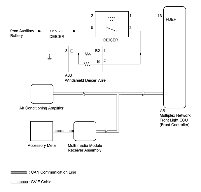
When the front deicer switch turns on, a front window deicer activation request signal from the air conditioning amplifier is sent via the CAN line to the multiplex network front light ECU (front controller). Then the multiplex network front light ECU (front controller) operates the windshield deicer.
WIRING DIAGRAM
INSPECTION PROCEDURE
Note
Inspect the fuses for circuits related to this system before performing the following inspection procedure.
Tech Tips
This circuit uses the CAN communication line. Before performing the inspection, check that the CAN communication system is functioning normally.
PROCEDURE
-
PERFORM ACTIVE TEST USING GTS (DEICER RELAY [FRONT])
-
Select the Active Test, using the GTS to generate a control command, and then check that the windshield deicer operates Click here.
Air Conditioner Tester Display Test Part Control Range Diagnostic Note Deicer Relay (Front) DEICER relay operation OFF / ON - OK Windshield deicer operates normally
NG 
INSPECT DEICER RELAY Click here
OK 
-
-
CHECK AIR CONDITIONING AMPLIFIER
-
Temporarily replace the air conditioning amplifier with a new or normally functioning one Click here.
-
Check that the malfunction disappears.
OK Malfunction disappears.
NG
CHECK MULTIPLEX NETWORK FRONT LIGHT ECU Click here
OK 
END (AIR CONDITIONING AMPLIFIER IS DEFECTIVE)
-
-
CHECK MULTIPLEX NETWORK FRONT LIGHT ECU
-
Temporarily replace the multiplex network front light ECU (front controller) with a new or normally functioning one.
-
Check that the malfunction disappears.
OK Malfunction disappears.
NG
CHECK MULTI-MEDIA MODULE RECEIVER ASSEMBLY Click here
OK
END (MULTIPLEX NETWORK FRONT LIGHT ECU [FRONT CONTROLLER] IS DEFECTIVE)
-
-
CHECK MULTI-MEDIA MODULE RECEIVER ASSEMBLY
-
Temporarily replace the multi-media module receiver assembly with a new or normally functioning one Click here.
-
Check that the malfunction disappears.
OK Malfunction disappears.
NG 
REPLACE ACCESSORY METER Click here
OK
END (MULTI-MEDIA MODULE RECEIVER IS DEFECTIVE)
-
-
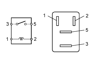
INSPECT DEICER RELAY
-
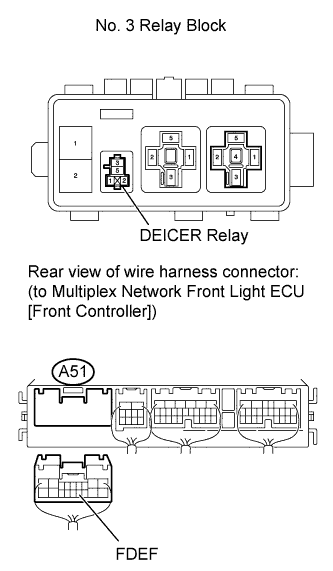
Remove the DEICER relay from the No. 3 relay block.
-
Measure the resistance according to the value(s) in the table below.
Standard resistance Tester Connection Condition Specified Condition 3 - 5 When battery voltage is not applied between terminals 10 kΩ or higher When battery voltage is applied to terminals 1 and 2 Below 1 Ω
NG
REPLACE DEICER RELAY
OK
-
-
CHECK HARNESS AND CONNECTOR (DEICER RELAY - MULTIPLEX NETWORK FRONT LIGHT ECU [FRONT CONTROLLER] AND BATTERY)
-
Remove the DEICER relay from the No. 3 relay block.
-
Disconnect the A51 multiplex network front light ECU (front controller) connector.
-
Measure the voltage according to the value(s) in the table below.
Standard voltage Tester Connection Condition Specified Condition DEICER relay terminal 2 - Body ground Always 11 to 14 V DEICER relay terminal 5 - Body ground Always 11 to 14 V -
Measure the resistance according to the value(s) in the table below.
Standard resistance Tester Connection Condition Specified Condition DEICER relay terminal 1 - A51-13 (FDEF) Always Below 1 Ω DEICER relay terminal 1 - Body ground Always 10 kΩ or higher
NG
REPAIR OR REPLACE HARNESS OR CONNECTOR
OK
-
-
CHECK HARNESS AND CONNECTOR (DEICER RELAY - WINDSHIELD GLASS AND BODY GROUND)
-
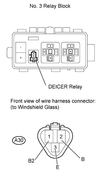
Remove the DEICER relay from the No. 3 relay block.
-
Disconnect the A30 windshield glass connector.
-
Measure the resistance according to the value(s) in the table below.
Standard resistance Tester Connection Condition Specified Condition A30-1 (B2) - DEICER relay terminal 3 Always Below 1 Ω A30-2 (B) - DEICER relay terminal 3 Always Below 1 Ω A30-3 (E) - Body ground Always Below 1 Ω DEICER relay terminal 3 - Body ground Always 10 kΩ or higher
NG
REPAIR OR REPLACE HARNESS OR CONNECTOR
OK
-
-
INSPECT WINDSHIELD GLASS
-
Inspect the windshield glass Click here.
Result Result Proceed to Windshield glass is broken A Windshield glass is not broken B
B
REPLACE WINDSHIELD GLASS Click here
A
-
-
CHECK MULTIPLEX NETWORK FRONT LIGHT ECU (FRONT CONTROLLER)
-
Temporarily replace the multiplex network front light ECU (front controller) with a new or normally functioning one.
-
Check that the malfunction disappears.
OK Malfunction disappears.
NG
REPLACE AIR CONDITIONING AMPLIFIER Click here
OK
END (MULTIPLEX NETWORK FRONT LIGHT ECU [FRONT CONTROLLER] IS DEFECTIVE)
-