PARKING ASSIST MONITOR SYSTEM Guide Lines are Displayed with Vehicle Center Line
DESCRIPTION
The television camera assembly can create parking guide lines. Since this function is not necessary on vehicles with the parking assist monitor system, the guide line creation function of the television camera assembly is disabled.
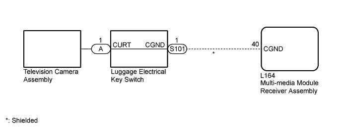
WIRING DIAGRAM
INSPECTION PROCEDURE
Note
-
When "System initializing" is displayed on the multi-media module display after disconnecting the cable from the negative (-) auxiliary battery terminal, correct the steering angle neutral point Click here.
-
Depending on the parts that are replaced or operations that are performed during vehicle inspection or maintenance, calibration of other systems as well as the parking assist monitor system may be needed Click here.
PROCEDURE
-
CHECK HARNESS AND CONNECTOR (TELEVISION CAMERA ASSEMBLY - BODY GROUND)
-
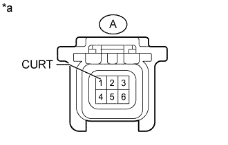
Text in Illustration *a Front view of Luggage Electrical Key Switch
(Television Camera Assembly Side)
Disconnect the television camera assembly connector.
-
Measure the resistance according to the value(s) in the table below.
Standard Resistance Tester Connection Condition Specified Condition A-1 (CURT) - Body ground Always Below 1 Ω
NG 
CHECK LUGGAGE ELECTRICAL KEY SWITCH Click here
OK 
REPLACE TELEVISION CAMERA ASSEMBLY Click here
-
-
CHECK LUGGAGE ELECTRICAL KEY SWITCH
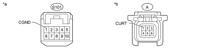
Text in Illustration *a Front view of Luggage Electrical Key Switch
(Wire Harness Side)
*b Front view of Luggage Electrical Key Switch
(Television Camera Assembly Side)
-
Disconnect the luggage electrical key switch connectors.
-
Measure the resistance according to the value(s) in the table below.
Standard Resistance Tester Connection Condition Specified Condition A-1 (CURT) - S101-1 (CGND) Always Below 1 Ω
NG 
REPLACE LUGGAGE ELECTRICAL KEY SWITCH Click here
OK
REPLACE MULTI-MEDIA MODULE RECEIVER ASSEMBLY Click here
-