G-BOOK SYSTEM, Diagnostic DTC:B15CB

| DTC Code | DTC Name |
|---|---|
| B15CB | Telematics Transceiver Antenna Disconnected |
DESCRIPTION
If an open circuit in the telephone antenna assembly is detected continuously for 1 minute as a result of a terminal check performed by the telematics transceiver every minute after the power switch is turned on (ACC), this DTC will be stored.
| DTC Code | DTC Detection Condition | Trouble Area |
|---|---|---|
| B15CB | DCM antenna is not connected or has an open circuit. |
|
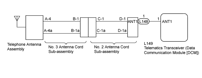
WIRING DIAGRAM
INSPECTION PROCEDURE
Tech Tips
When replacing the multi-media module receiver assembly or the telematics transceiver, perform the vehicle contract setting Click here.
PROCEDURE
-
CLEAR DTC
-
Clear the DTC Click here.
NEXT 
-
-
CHECK DTC
-
Check for DTCs and check if the same DTC is output again Click here.
OK No DTC is output.
NG 
INSPECT TELEPHONE ANTENNA ASSEMBLY Click here
OK 
USE SIMULATION METHOD TO CHECK Click here
-
-
INSPECT TELEPHONE ANTENNA ASSEMBLY
-
Check the installation condition.
-
Check the telephone antenna assembly for any installation problems.
OK The telephone antenna assembly is installed correctly.
-
-
Disconnect the telephone antenna connector.
-
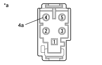
Text in Illustration *a Component without harness connected
(Telephone Antenna Assembly)
Measure the resistance according to the value(s) in the table below.
Standard Resistance Tester Connection Condition Specified Condition 4 - 1a Always 4 to 11 kΩ
NG 
REPLACE TELEPHONE ANTENNA ASSEMBLY Click here
OK
-
-
INSPECT NO. 3 ANTENNA CORD SUB-ASSEMBLY
-
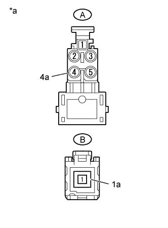
Text in Illustration *a No. 3 Antenna Cord Sub-assembly Disconnect the No. 3 antenna cord sub-assembly from the telephone antenna connector.
-
Disconnect the No. 3 antenna cord sub-assembly from the No. 2 antenna cord sub-assembly.
-
Measure the resistance according to the value(s) in the table below.
Standard Resistance Tester Connection Condition Specified Condition A-4 - B-1 Always Below 1 Ω A-4a - B-1a Always Below 1 Ω A-4 - Body ground Always 10 kΩ or higher A-4a - Body ground Always 10 kΩ or higher
NG
REPLACE NO. 3 ANTENNA CORD SUB-ASSEMBLY
OK
-
-
INSPECT NO. 2 ANTENNA CORD SUB-ASSEMBLY
-
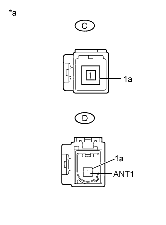
Text in Illustration *a No. 2 Antenna Cord Sub-assembly Disconnect the No. 2 antenna cord sub-assembly from the No. 3 antenna cord sub-assembly.
-
Disconnect the No. 2 antenna cord sub-assembly from the antenna cord sub-assembly.
-
Measure the resistance according to the value(s) in the table below.
Standard Resistance Tester Connection Condition Specified Condition C-1 - D-1 (ANT1) Always Below 1 Ω C-1a - D-1a Always Below 1 Ω C-1 - Body ground Always 10 kΩ or higher C-1a - Body ground Always 10 kΩ or higher
NG
REPLACE NO. 2 ANTENNA CORD SUB-ASSEMBLY
OK
-
-
CHECK HARNESS AND CONNECTOR (NO. 2 ANTENNA CORD SUB-ASSEMBLY - TELEMATICS TRANSCEIVER)
-
Disconnect the L148 No. 2 antenna cord sub-assembly connector.
-
Disconnect the L149 telematics transceiver connector.
-
Measure the resistance according to the value(s) in the table below.
Standard Resistance Tester Connection Condition Specified Condition L148-1 (ANT1) - L149-1 (ANT1) Always Below 1 Ω L148-1 (ANT1) - Body ground Always 10 kΩ or higher
NG
REPAIR OR REPLACE HARNESS OR CONNECTOR
OK
-
-
REPLACE TELEMATICS TRANSCEIVER
-
Replace the telematics transceiver with a known good one Click here.
NEXT
-
-
CHECK DTC
-
Check for DTCs and check if the same DTC is output again Click here.
OK No DTC is output.
NG
REPLACE MULTI-MEDIA MODULE RECEIVER ASSEMBLY Click here
OK
END (TELEMATICS TRANSCEIVER IS DEFECTIVE)
-