MULTI-DISPLAY INSTALLATION

Tech Tips
-
Use the same procedure for RHD and LHD vehicles.
-
The procedure listed below is for LHD vehicles.
-
A bolt without a torque specification is shown in the standard bolt chart Click here.
-
INSTALL NO. 1 COMBINATION METER BRACKET
-
Install the accessory meter bracket with the 2 bolts.
-
-
INSTALL ACCESSORY METER ASSEMBLY
-
Connect all the connectors.
-
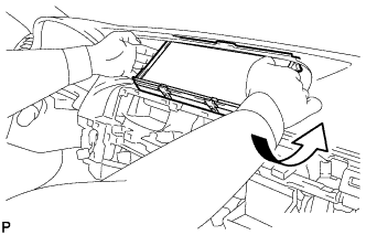
Move the accessory meter assembly in the direction of the arrow in the illustration to temporarily install it.
-
Install the accessory meter assembly with the 4 bolts.
-
-
INSTALL INSTRUMENT PANEL FINISH PANEL SUB-ASSEMBLY
-
Attach the 10 clips to install the instrument panel finish panel sub-assembly.
-
-
INSTALL INSTRUMENT CLUSTER FINISH PANEL GARNISH ASSEMBLY
-
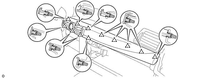
Connect each connector.
-
Attach the 12 clips to install the instrument cluster finish panel garnish assembly.
-
-
INSTALL MULTI-MEDIA MODULE RECEIVER ASSEMBLY
-
Connect the connectors.
-
Insert the multi-media module receiver assembly with bracket.
Note
When inserting the radio receiver, do not press the knobs on it.
-
Attach the 6 clips.
-
Install the multi-media module receiver assembly with bracket with the 2 bolts.
-
-
INSTALL LOWER NO. 1 INSTRUMENT PANEL FINISH PANEL
-
Connect the connector.
-
Attach the 5 guides and 4 clips to install the lower No. 1 instrument panel finish panel.
-
-
INSTALL LOWER NO. 2 INSTRUMENT PANEL FINISH PANEL
-
Attach the 5 guides and 4 clips to install the lower No. 2 instrument panel finish panel.
-
-
INSTALL UPPER CONSOLE PANEL SUB-ASSEMBLY
-
Attach the 6 clips to install the upper console panel sub-assembly.
-
Connect the connector.
-
-
INSTALL UPPER INSTRUMENT CLUSTER FINISH PANEL
-
Attach the 5 clips to install the upper instrument cluster finish panel.
-
-
INSTALL UPPER REAR CONSOLE PANEL SUB-ASSEMBLY
-
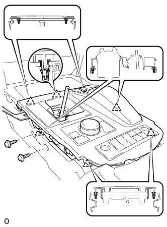
Connect each connector and attach each wire harness clamp.
-
Attach the 6 clips to install the upper rear console panel sub-assembly.
-
Install the 2 screws.
-
-
INSTALL NO. 3 BOX PANEL
-
Attach the 4 claws to install the No. 3 box panel.
-
-
INSTALL SHIFT LEVER KNOB SUB-ASSEMBLY
-
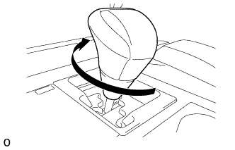
Twist the shift lever knob sub-assembly in the direction indicated by the arrow to install it.
-
-
INSTALL INSTRUMENT PANEL FINISH PANEL END RH
Tech Tips
Use the same procedure described for the LH side.
-
INSTALL INSTRUMENT PANEL FINISH PANEL END LH
-
Attach the rear part of the instrument panel finish panel end LH 3 clips.
-
Attach the front part of the instrument panel finish panel end LH 6 clips to install the instrument panel finish panel end LH.
-
-
CONNECT CABLE TO AUXILIARY BATTERY NEGATIVE TERMINAL
Note
When disconnecting the cable, some systems need to be initialized after the cable is reconnected Click here
-
INSTALL BATTERY SERVICE HOLE COVER LH
-

Text in Illustration *A for Standard *B for Ottoman Attach the battery service hole cover LH with the clip and fastening tape.
-
-
INSTALL DECK TRIM SIDE BOARD LH (w/o Spare Tire)
-

Attach the 2 clips to install the deck trim side board LH.
-
-
INSTALL DECK BOARD ASSEMBLY (w/o Spare Tire)

-
INSTALL LUGGAGE COMPARTMENT MAT SUB-ASSEMBLY (w/ Spare Tire)
