NAVIGATION SYSTEM Steering Pad Switch Circuit
DESCRIPTION
This circuit sends an operation signal from the steering pad switch assembly to the multi-media module receiver assembly.
If there is an open in the circuit, the audio system cannot be operated using the steering pad switch assembly.
If there is a short in the circuit, the same condition as when a switch is continuously depressed occurs.
Therefore, the multi-media module receiver assembly cannot be operated using the steering pad switch assembly, and also the multi-media module receiver assembly itself cannot function.
WIRING DIAGRAM
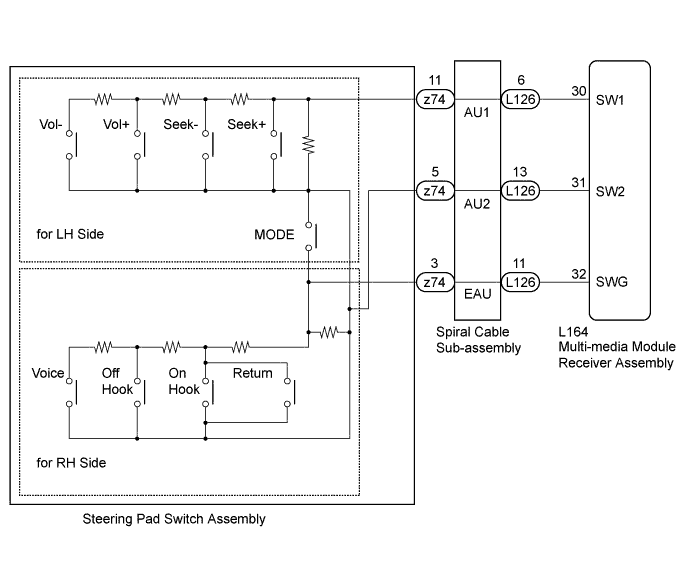
INSPECTION PROCEDURE
Note
-
The vehicle is equipped with a Supplemental Restraint System (SRS) which includes components such as airbags. Before servicing (including removal or installation of parts), be sure to read the precaution for Supplemental Restraint System Click here.
-
Depending on the parts that are replaced during vehicle inspection or maintenance, performing initialization, registration or calibration may be needed. Refer to Precaution for Navigation System Click here.
PROCEDURE
-
INSPECT STEERING PAD SWITCH ASSEMBLY
-
Remove the steering pad switch assembly Click here.
-
Inspect the steering pad switch assembly Click here.
NG 
REPLACE STEERING PAD SWITCH ASSEMBLY Click here
OK 
-
-
INSPECT SPIRAL CABLE SUB-ASSEMBLY
-
Remove the spiral cable sub-assembly Click here.
-
Inspect the spiral cable sub-assembly Click here.
NG
REPLACE SPIRAL CABLE SUB-ASSEMBLY Click here
OK
-
-
CHECK HARNESS AND CONNECTOR (MULTI-MEDIA MODULE RECEIVER ASSEMBLY - SPIRAL CABLE SUB-ASSEMBLY)
-
Disconnect the L164 multi-media module receiver assembly connector.
-
Disconnect the L126 spiral cable sub-assembly connector.
-
Measure the resistance according to the value(s) in the table below.
Standard Resistance Tester Connection Switch Condition Specified Condition L164-30 (SW1) - L126-6 (AU1) Always Below 1 Ω L164-31 (SW2) - L126-13 (AU2) Always Below 1 Ω L164-32 (SWG) - L126-11 (EAU) Always Below 1 Ω L164-30 (SW1) - Body ground Always 10 kΩ or higher L164-31 (SW2) - Body ground Always 10 kΩ or higher L164-32 (SWG) - Body ground Always 10 kΩ or higher
NG
REPAIR OR REPLACE HARNESS OR CONNECTOR
OK 
PROCEED TO NEXT SUSPECTED AREA SHOWN IN PROBLEM SYMPTOMS TABLE Click here
-