| DTC Code | DTC Name |
|---|---|
| Switch Lights of Remote Touch Always Illuminate or cannot be Controlled Using Rheostat |
DESCRIPTION
Power is supplied to the remote touch illumination when the light control switch is in the tail or head position.
-
When the remote touch is in self check mode, the switch illumination on the remote touch may remain on.
-
If any illumination controlled by the rheostat switch has a malfunction such as an open circuit, the switch illumination of the remote touch is affected and cannot be controlled by the rheostat switch.
INSPECTION PROCEDURE
Inspect the fuses for circuits related to this system before performing the following inspection procedure.
PROCEDURE
- Click here
CHECK ILLUMINATION CONTROLLED BY RHEOSTAT SWITCH
-
Perform the following procedure and check that the illumination controlled by the rheostat switch illuminates properly.
-
If the vehicle is in a bright area, move it to a dark area.
Tip:When the vehicle is in a bright area, the switch illumination may not turn on due to the auto dimmer function.
-
If the light control switch is in the AUTO position, turn the switch to the tail or head position.
Tip:If the light control switch is in the AUTO position, the switch illumination will not turn on unless the surrounding area is dark.
Table 1. Result Result Proceed to Any of the illumination controlled by the rheostat switch does not illuminate properly. A All of the illumination controlled by the rheostat switch illuminates properly. B Tip:The shift lever illumination and panel switch illumination are controlled by the rheostat switch. If either of these has a malfunction such as an open circuit, the switch illumination of the remote touch is affected and cannot be controlled by the rheostat switch.
-
-
- Click here
REPAIR OR REPLACE ILLUMINATION CONTROLLED BY RHEOSTAT SWITCH
-
Repair or replace the part with the malfunctioning illumination that is controlled by the rheostat switch.
- NEXTClick here
-
- Click here
CONFIRM SYMPTOMS
-
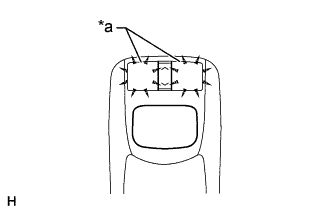
Perform the following procedure, operate the rheostat switch again, and check if illumination brightness adjustment is possible (including adjustment of other devices such as the multi-media module receiver assembly).
Table 2. Text in Illustration *a Switch Illumination
-
Check if the remote touch is in self check mode. If it is, cancel self check mode (Click here).
Tip:When the remote touch is in self check mode, the switch illumination on the remote touch may remain on.
-
If the vehicle is in a bright area, move it to a dark area.
Tip:When the vehicle is in a bright area, the switch illumination may not turn on due to the auto dimmer function.
-
If the light control switch is in the AUTO position, turn the switch to the tail or head position.
Tip:If the light control switch is in the AUTO position, the switch illumination will not turn on unless the surrounding area is dark.
Table 3. Result Result Proceed to Switch illumination cannot be adjusted (illumination for other devices can be adjusted). A Switch illumination cannot be adjusted (illumination for other devices also cannot be adjusted). B Switch illumination can be adjusted. C
-
-
- Click here
REMOTE TOUCH SELF CHECK (SWITCH ILLUMINATION CHECK)
-
Activate self check mode (Click here).
-
Check the switch illumination.
-
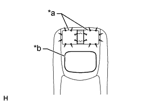
Move the remote touch switch knob from the lower left to the upper right to check that the brightness of the switch illumination changes.
OK The brightness of the switch illumination changes according to remote touch switch knob operation. Table 4. Text in Illustration *a Switch Illumination *b Switch Knob
-
- OKClick here
- NGClick here
-
- Click here
CHECK HARNESS AND CONNECTOR (ILLUMINATION SIGNAL)
-
Disconnect the remote touch (remote operation board) connector.
-
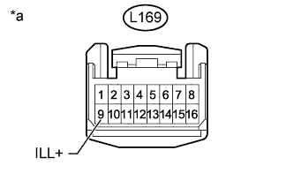
Measure the voltage according to the value(s) in the table below.
Standard Voltage Tester Connection Switch Condition Specified Condition L169-9 (ILL+) - Body ground Light control switch in tail or head position 11 to 14 V Table 5. Text in Illustration *a Front view of wire harness connector
(to Remote Touch [Remote Operation Board])
- OKClick here
- NGClick here
-
- Click here
CHECK HARNESS AND CONNECTOR (REMOTE TOUCH [REMOTE OPERATION BOARD] - NO. 1 METER ECU SUB-ASSEMBLY)
-
Disconnect the L169 remote touch (remote operation board) connector.
-
Disconnect the L124 No. 1 meter ECU sub-assembly connector.
-
Measure the resistance according to the value(s) in the table below.
Standard Resistance Tester Connection Condition Specified Condition L169-16 (ILL-) - L124-16 (ILL-) Always Below 1 Ω L169-16 (ILL-) - Body ground Always 10 kΩ or higher
- OKClick here
- NGClick here
-
- Click here
REPLACE REMOTE TOUCH (REMOTE OPERATION BOARD)Click here
- Click here
GO TO METER / GAUGE SYSTEMClick here
- Click here
END
- Click here
REPLACE REMOTE TOUCH (REMOTE OPERATION BOARD)Click here
- Click here
REPAIR OR REPLACE HARNESS OR CONNECTOR
- Click here
REPAIR OR REPLACE HARNESS OR CONNECTOR