DESCRIPTION
The rear power seat switch and multi-media module receiver assembly are connected by the AVC-LAN communication line. When an AVC-LAN communication error occurs between the rear power seat switch (audio switch) and the multi-media module receiver assembly, this DTC will be stored.
| DTC Code | DTC Detection Condition | Trouble Area |
|---|---|---|
| B15DA | A device that is listed in the AVC-LAN connected device record of the master unit is missing. |
|
INSPECTION PROCEDURE
Inspect the fuses for circuits related to this system before performing the following inspection procedure.
PROCEDURE
- Click here
CLEAR DTC
-
Clear the DTCs (Click here).
- NEXTClick here
-
- Click here
CHECK DTC
-
Recheck for DTCs and check if the same DTC is output again (Click here).
OK No DTCs are output.
- OKClick here
- NGClick here
-
- Click here
CHECK HARNESS AND CONNECTOR (REAR POWER SEAT SWITCH [AUDIO SWITCH] - AUXILIARY BATTERY AND BODY GROUND)
-
Disconnect the rear power seat switch (audio switch) connector.
-
Measure the resistance according to the value(s) in the table below.
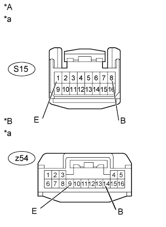
Standard Resistance for 4-Passenger with Ottoman Tester Connection Condition Specified Condition S15-1 (E) - Body ground Always Below 1 Ω except 4-Passenger with Ottoman Tester Connection Condition Specified Condition z54-9 (E) - Body ground Always Below 1 Ω -
Measure the voltage according to the value(s) in the table below.
Standard Voltage for 4-Passenger with Ottoman Tester Connection Condition Specified Condition S15-8 (B) - Body ground Always 11 to 14 V except 4-Passenger with Ottoman Tester Connection Condition Specified Condition z54-14 (B) - Body ground Always 11 to 14 V Table 1. Text in Illustration *A for 4-Passenger with Ottoman *B except 4-Passenger with Ottoman *a Front view of wire harness connector
(to Rear Power Seat Switch [Audio Switch])
- OKClick here
- NGClick here
-
- Click here
CHECK HARNESS AND CONNECTOR (REAR POWER SEAT MODULE SWITCH [AUDIO SWITCH] - ACCESSORY METER ASSEMBLY)
-
Disconnect the S15*1 or z54*2 rear power seat switch (audio switch) connector.
-
*1: for 4-Passenger with Ottoman
-
*2: except 4-Passenger with Ottoman
-
-
Disconnect the L163 accessory meter assembly connector.
-
Measure the resistance according to the value(s) in the table below.
Standard Resistance for 4-Passenger with Ottoman Tester Connection Condition Specified Condition S15-4 (TX+) - L163-6 (TX1+) Always Below 1 Ω S15-3 (TX-) - L163-18 (TX1-) Always Below 1 Ω S15-4 (TX+) - Body ground Always 10 kΩ or higher S15-3 (TX-) - Body ground Always 10 kΩ or higher except 4-Passenger with Ottoman Tester Connection Condition Specified Condition z54-10 (TX+) - L163-6 (TX1+) Always Below 1 Ω z54-11 (TX-) - L163-18 (TX1-) Always Below 1 Ω z54-10 (TX+) - Body ground Always 10 kΩ or higher z54-11 (TX-) - Body ground Always 10 kΩ or higher
- OKClick here
- NGClick here
-
- Click here
CHECK REAR POWER SEAT SWITCH
-
Replace the rear power seat switch with a new or normally functioning one.
-
for Power Seat:Click here
-
for 4-Passenger with Ottoman:Click here
-
for 5-Passenger with Ottoman:Click here
-
for Fixed Seat Type:Click here
-
- NEXTClick here
-
- Click here
CLEAR DTC
-
Clear the DTCs (Click here).
- NEXTClick here
-
- Click here
CHECK DTC
-
Recheck for DTCs and check if the same DTC is output again (Click here).
OK No DTCs are output.
- OKClick here
- NGClick here
-
- Click here
END (COMMUNICATION MALFUNCTION DUE TO NOISE)
- Click here
REPAIR OR REPLACE HARNESS OR CONNECTOR
- Click here
REPAIR OR REPLACE HARNESS OR CONNECTOR
- Click here
REPLACE ACCESSORY METER ASSEMBLYClick here
- Click here
END (REAR POWER SEAT SWITCH [AUDIO SWITCH] IS DEFECTIVE)