NETWORK GATEWAY ECU (for RHD) REMOVAL

-
PRECAUTION
CAUTION:
After turning the power switch off, waiting time may be required before disconnecting the cable from the auxiliary battery negative (-) terminal. Therefore, make sure to read the disconnecting the cable from the auxiliary battery negative (-) terminal notices before proceeding with work Click here.
-
REMOVE LUGGAGE COMPARTMENT MAT SUB-ASSEMBLY (w/ Spare Tire)

-
REMOVE DECK BOARD ASSEMBLY (w/o Spare Tire)

-
REMOVE DECK TRIM SIDE BOARD LH (w/o Spare Tire)
-

Detach the 2 clips and remove the deck trim side board LH.
-
-
REMOVE BATTERY SERVICE HOLE COVER LH
-

Text in Illustration *A for Standard *B for Ottoman *1 Fastening Tape Detach the clip, fastening tape and remove the battery service hole cover LH.
-
-
DISCONNECT CABLE FROM AUXILIARY BATTERY NEGATIVE TERMINAL
CAUTION:
Wait at least 90 seconds after disconnecting the cable from the auxiliary battery negative (-) terminal to disable the SRS system.
Note
When disconnecting the cable, some systems need to be initialized after the cable is reconnected Click here.
-
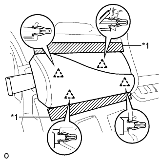
REMOVE INSTRUMENT SIDE PANEL RH
Text in Illustration *1 Protective Tape
-
Apply protective tape as shown in the illustration.
-
Using moulding remover D, detach the 6 clips and remove the instrument side panel RH.
-
-
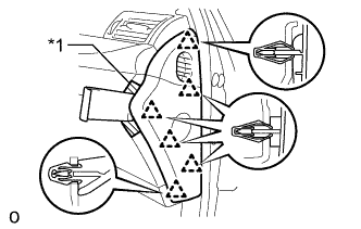
REMOVE INSTRUMENT PANEL ORNAMENT
Text in Illustration *1 Protective Tape
-
Apply protective tape as shown in the illustration.
-
Using moulding remover B, detach the 4 clips and remove the instrument panel ornament.
-
Disconnect the connector.
-
-
REMOVE NO. 1 INSTRUMENT PANEL SAFETY PAD SUB-ASSEMBLY
-
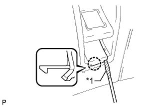
Text in Illustration *1 Protective Tape Using a screwdriver, detach the claw and remove the switch base hole cover from the No. 1 instrument panel safety pad sub-assembly.
Tech Tips
Tape the screwdriver tip before use.
-
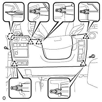
Remove the bolt.
-
Remove the screw <C>.
-
Detach the 5 clips and claw and remove the No. 1 instrument panel safety pad sub-assembly.
-
Disconnect each connector.
-
-
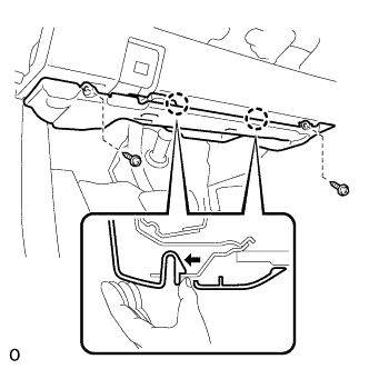
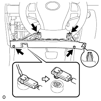
REMOVE NO. 1 INSTRUMENT PANEL UNDER COVER SUB-ASSEMBLY
-
Remove the 2 screws.
-
Detach the 2 claws as shown in the illustration and remove the No. 1 instrument panel under cover sub-assembly.
-
Detach the 2 claws and disconnect the DLC3.
-
Disconnect each connector and detach each wire harness clamp.
-
-
REMOVE DRIVER SIDE KNEE AIRBAG ASSEMBLY
CAUTION:
When storing the driver side knee airbag assembly, keep the airbag deployment side facing upward.
-
Check that the power switch is off.
-
Check that the cable is disconnected from the negative (-) auxiliary battery terminal.
CAUTION:
Wait at least 90 seconds after disconnecting the cable from the negative (-) auxiliary battery terminal to disable the SRS system.
-
Remove the 4 bolts.
-
Detach the clip and remove the driver side knee airbag assembly.
-
Detach the claw to disconnect the hood lock control lever sub-assembly from the driver side knee airbag assembly.
-
Using a screwdriver release the airbag connector lock.
-
Disconnect the airbag connector.
Note
When disconnecting airbag connector, take care not to damage the airbag wire harness.
-
-
REMOVE NETWORK GATEWAY ECU
-
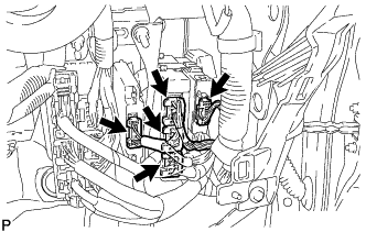
Disconnect each connector.
-
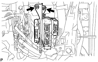
Remove the 2 nuts and No. 1 ECU integration bracket.
-
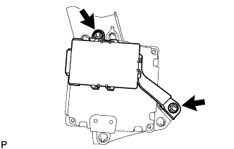
Remove the 2 nuts and network gateway ECU.
-