REAR SEAT ENTERTAINMENT SYSTEM, Diagnostic DTC:B156D

| DTC Code | DTC Name |
|---|---|
| B156D | Blu-ray Disc Player Disconnected |
DESCRIPTION
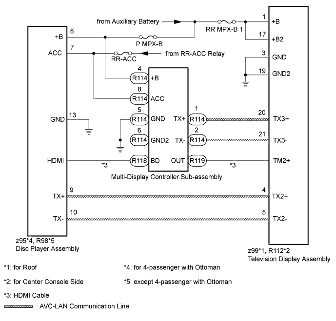
The disc player assembly and television display assembly are connected by the AVC-LAN communication line.
The multi-display controller sub-assembly, disc player assembly and television display assembly are connected by the HDMI cable.
When an AVC-LAN communication and HDMI cable communication error occurs between the disc player assembly and television display assembly, this DTC will be stored.
| DTC Code | DTC Detection Condition | Trouble Area |
|---|---|---|
| B156D | When either condition below is met:
|
|
Tech Tips
-
Even if no fault is present, this DTC may be stored depending on the battery condition or engine start voltage.
-
The television display assembly is the master unit.
WIRING DIAGRAM
INSPECTION PROCEDURE
Note
Inspect the fuses and relays for circuits related to this system before performing the following inspection procedure.
PROCEDURE
-
CLEAR DTC
Clear the DTCs Click here.
NEXT 
-
CHECK FOR DTC
-
Recheck for DTCs and check if the same DTC is output again Click here.
OK No DTCs are output.
NG 
CHECK CONNECTOR CONNECTION CONDITION Click here
OK 
USE SIMULATION METHOD TO CHECK Click here
-
-
CHECK CONNECTOR CONNECTION CONDITION
-
Check that the television display assembly, multi-display controller sub-assembly and disc player assembly connectors are connected properly.
OK Connectors connected properly.
NG 
CONNECT CONNECTOR CORRECTLY Click here
OK
-
-
CHECK HARNESS AND CONNECTOR (TELEVISION DISPLAY ASSEMBLY - BATTERY AND BODY GROUND)
-
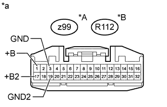
Text in Illustration *A for Roof *B for Center Console Side *a Front view of wire harness connector
(to Television Display Assembly)
Disconnect the television display assembly connector.
-
Measure the resistance according to the value(s) in the table below.
Standard Resistance for Roof Tester Connection Condition Specified Condition z99-3 (GND) - Body ground Always Below 1 Ω z99-19 (GND2) - Body ground Always Below 1 Ω for Center Console Side Tester Connection Condition Specified Condition R112-3 (GND) - Body ground Always Below 1 Ω R112-19 (GND2) - Body ground Always Below 1 Ω -
Measure the voltage according to the value(s) in the table below.
Standard Voltage for Roof Tester Connection Switch Condition Specified Condition z99-1 (+B) - Body ground Power switch off 11 to 14 V z99-17 (+B2) - Body ground Power switch off 11 to 14 V for Center Console Side Tester Connection Switch Condition Specified Condition R112-1 (+B) - Body ground Power switch off 11 to 14 V R112-17 (+B2) - Body ground Power switch off 11 to 14 V
NG
REPAIR OR REPLACE HARNESS OR CONNECTOR
OK
-
-
CHECK HARNESS AND CONNECTOR (DISC PLAYER ASSEMBLY - BATTERY AND BODY GROUND)
-
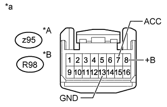
Text in Illustration *A for 4-passenger with Ottoman *B except 4-passenger with Ottoman *a Front view of wire harness connector
(to Disc Player Assembly)
Disconnect the disc player assembly connector.
-
Measure the resistance according to the value(s) in the table below.
Standard Resistance for 4-passenger with Ottoman Tester Connection Condition Specified Condition z95-13 (GND) - Body ground Always Below 1 Ω except 4-passenger with Ottoman Tester Connection Condition Specified Condition R98-13 (GND) - Body ground Always Below 1 Ω -
Measure the voltage according to the value(s) in the table below.
Standard Voltage for 4-passenger with Ottoman Tester Connection Switch Condition Specified Condition z95-8 (+B) - Body ground Power switch off 11 to 14 V z95-7 (ACC) - Body ground Power switch on (ACC) 11 to 14 V except 4-passenger with Ottoman Tester Connection Switch Condition Specified Condition R98-8 (+B) - Body ground Power switch off 11 to 14 V R98-7 (ACC) - Body ground Power switch on (ACC) 11 to 14 V
NG
REPAIR OR REPLACE HARNESS OR CONNECTOR
OK
-
-
CHECK HARNESS AND CONNECTOR (MULTI-DISPLAY CONTROLLER SUB-ASSEMBLY - BATTERY AND BODY GROUND)
-
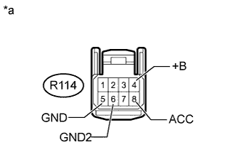
Text in Illustration *a Front view of wire harness connector
(to Multi-display Controller Sub-assembly)
Disconnect the multi-display controller sub-assembly connector.
-
Measure the resistance according to the value(s) in the table below.
Standard Resistance Tester Connection Condition Specified Condition R114-5 (GND) - Body ground Always Below 1 Ω R114-6 (GND2) - Body ground Always Below 1 Ω -
Measure the voltage according to the value(s) in the table below.
Standard Voltage Tester Connection Switch Condition Specified Condition R114-4 (+B) - Body ground Power switch off 11 to 14 V R114-8 (ACC) - Body ground Power switch on (ACC) 11 to 14 V
NG
REPAIR OR REPLACE HARNESS OR CONNECTOR
OK
-
-
CHECK HARNESS AND CONNECTOR (TELEVISION DISPLAY ASSEMBLY - DISC PLAYER ASSEMBLY AND MULTI-DISPLAY CONTROLLER SUB-ASSEMBLY)
-
*1: for 4-passenger with Ottoman
-
*2: except 4-passenger with Ottman
-
for Roof:
-
Disconnect the z99 television display assembly connector.
-
Disconnect the z95*1 or R98*2 disc player assembly connector.
-
Disconnect the R114 multi-display controller sub-assembly connector.
-
Measure the resistance according to the value(s) in the table below.
Standard Resistance for 4-passenger with Ottoman Tester Connection Condition Specified Condition z99-4 (TX2+) - z95-9 (TX+) Always Below 1 Ω z99-5 (TX2-) - z95-10 (TX-) Always Below 1 Ω z99-20 (TX3+) - R114-1 (TX+) Always Below 1 Ω z99-21 (TX3-) - R114-2 (TX-) Always Below 1 Ω z99-4 (TX2+) or z95-9 (TX+) - Body ground Always 10 kΩ or higher z99-5 (TX2-) or z95-10 (TX-) - Body ground Always 10 kΩ or higher z99-20 (TX3+) or R114-1 (TX+) - Body ground Always 10 kΩ or higher z99-21 (TX3-) or R114-2 (TX-) - Body ground Always 10 kΩ or higher except 4-passenger with Ottoman Tester Connection Condition Specified Condition z99-4 (TX2+) - R98-9 (TX+) Always Below 1 Ω z99-5 (TX2-) - R98-10 (TX-) Always Below 1 Ω z99-20 (TX3+) - R114-1 (TX+) Always Below 1 Ω z99-21 (TX3-) - R114-2 (TX-) Always Below 1 Ω z99-4 (TX2+) or R98-9 (TX+) - Body ground Always 10 kΩ or higher z99-5 (TX2-) or R98-10 (TX-) - Body ground Always 10 kΩ or higher z99-20 (TX3+) or R114-1 (TX+) - Body ground Always 10 kΩ or higher z99-21 (TX3-) or R114-2 (TX-) - Body ground Always 10 kΩ or higher
-
-
for Center Console Side:
-
Disconnect the R112 television display assembly connector.
-
Disconnect the z95*1 or R98*2 disc player assembly connector.
-
Disconnect the R114 multi-display controller sub-assembly connector.
-
Measure the resistance according to the value(s) in the table below.
Standard Resistance for 4-passenger with Ottoman Tester Connection Condition Specified Condition R112-4 (TX2+) - z95-9 (TX+) Always Below 1 Ω R112-5 (TX2-) - z95-10 (TX-) Always Below 1 Ω R112-20 (TX3+) - R114-1 (TX+) Always Below 1 Ω R112-21 (TX3-) - R114-2 (TX-) Always Below 1 Ω R112-4 (TX2+) or z95-9 (TX+) - Body ground Always 10 kΩ or higher R112-5 (TX2-) or z95-10 (TX-) - Body ground Always 10 kΩ or higher R112-20 (TX3+) or R114-1 (TX+) - Body ground Always 10 kΩ or higher R112-21 (TX3-) or R114-2 (TX-) - Body ground Always 10 kΩ or higher except 4-passenger with Ottoman Tester Connection Condition Specified Condition R112-4 (TX2+) - R98-9 (TX+) Always Below 1 Ω R112-5 (TX2-) - R98-10 (TX-) Always Below 1 Ω R112-20 (TX3+) - R114-1 (TX+) Always Below 1 Ω R112-21 (TX3-) - R114-2 (TX-) Always Below 1 Ω R112-4 (TX2+) or R98-9 (TX+) - Body ground Always 10 kΩ or higher R112-5 (TX2-) or R98-10 (TX-) - Body ground Always 10 kΩ or higher R112-20 (TX3+) or R114-1 (TX+) - Body ground Always 10 kΩ or higher R112-21 (TX3-) or R114-2 (TX-) - Body ground Always 10 kΩ or higher
-
NG
REPAIR OR REPLACE HARNESS OR CONNECTOR
OK
-
-
CHECK HARNESS AND CONNECTOR (HDMI CABLE)
-
Replace the harness and connector (HDMI cable) with a new or known good one.
NEXT
-
-
CLEAR DTC
-
Clear the DTCs Click here.
NEXT
-
-
CHECK FOR DTC
-
Recheck for DTCs and check if the same DTC is output again Click here.
OK No DTCs are output.
NG
REPLACE TELEVISION DISPLAY ASSEMBLY Click here
OK
END (HDMI CABLE IS DEFECTIVE)
-
-
REPLACE TELEVISION DISPLAY ASSEMBLY
-
Replace the television display assembly with a new or known good one.
-
for Roof: Click here.
-
for Center Console Side: Click here.
-
NEXT
-
-
CLEAR DTC
-
Clear the DTCs Click here.
NEXT
-
-
CHECK FOR DTC
-
Recheck for DTCs and check if the same DTC is output again Click here.
OK No DTCs are output.
NG
REPLACE MULTI-DISPLAY CONTROLLER SUB-ASSEMBLY Click here
OK
END (TELEVISION DISPLAY ASSEMBLY IS DEFECTIVE)
-
-
REPLACE MULTI-DISPLAY CONTROLLER SUB-ASSEMBLY
-
Replace the multi-display controller sub-assembly with a new or known good one Click here.
NEXT
-
-
CLEAR DTC
-
Clear the DTCs Click here.
NEXT
-
-
CHECK FOR DTC
-
Recheck for DTCs and check if the same DTC is output again Click here.
OK No DTCs are output. Result Result Proceed to OK A NG (for 4-passenger with Ottoman) B NG (for 5-passenger with Ottoman) C NG (except Ottoman) D
B
REPLACE DISC PLAYER ASSEMBLY Click here
C
REPLACE DISC PLAYER ASSEMBLY Click here
D
REPLACE DISC PLAYER ASSEMBLY Click here
A
END (MULTI-DISPLAY CONTROLLER SUB-ASSEMBLY IS DEFECTIVE)
-