REAR SEAT ENTERTAINMENT SYSTEM Sound Signal Circuit between Headphone Terminal and Television Display
DESCRIPTION
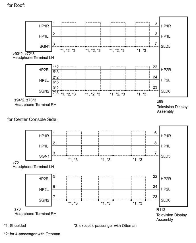
This is the sound signal circuit between the television display assembly and headphone terminal.
WIRING DIAGRAM
INSPECTION PROCEDURE
PROCEDURE
-
CHECK HARNESS AND CONNECTOR (TELEVISION DISPLAY ASSEMBLY - HEADPHONE TERMINAL)
-
*1: for 4-passenger with Ottoman
-
*2: except 4-passenger with Ottoman
-
for Roof:
-
Disconnect the z99 television display assembly connector.
-
Disconnect the z93*1 or z72*2 headphone terminal LH connectors.
-
Disconnect the z94*1 or z73*2 headphone terminal RH connectors
-
Measure the resistance according to the value(s) in the table below.
Standard Resistance for 4-passenger with Ottoman Tester Connection Condition Specified Condition z99-6 (HP1R) - z93-1 (HP1R) Always Below 1 Ω z99-8 (HP1L) - z93-2 (HP1L) Always Below 1 Ω z99-7 (SLD5) - z93-3 (SGN1) Always Below 1 Ω z99-22 (HP2R) - z94-1 (HP2R) Always Below 1 Ω z99-24 (HP2L) - z94-2 (HP2L) Always Below 1 Ω z99-23 (SLD6) - z94-3 (SGN2) Always Below 1 Ω z99-6 (HP1R) or z93-1 (HP1R) - Body ground Always 10 kΩ or higher z99-8 (HP1L) or z93-2 (HP1L) - Body ground Always 10 kΩ or higher z99-7 (SLD5) or z93-3 (SGN1) - Body ground Always 10 kΩ or higher z99-22 (HP2R) or z94-1 (HP2R) - Body ground Always 10 kΩ or higher z99-24 (HP2L) or z94-2 (HP2L) - Body ground Always 10 kΩ or higher z99-23 (SLD6) or z94-3 (SGN2) - Body ground Always 10 kΩ or higher except 4-passenger with Ottoman Tester Connection Condition Specified Condition z99-6 (HP1R) - z72-1 (HP1R) Always Below 1 Ω z99-8 (HP1L) - z72-2 (HP1L) Always Below 1 Ω z99-7 (SLD5) - z72-3 (SGN1) Always Below 1 Ω z99-22 (HP2R) - z73-5 (HP2R) Always Below 1 Ω z99-24 (HP2L) - z73-6 (HP2L) Always Below 1 Ω z99-23 (SLD6) - z73-7 (SGN2) Always Below 1 Ω z99-6 (HP1R) or z72-1 (HP1R) - Body ground Always 10 kΩ or higher z99-8 (HP1L) or z72-2 (HP1L) - Body ground Always 10 kΩ or higher z99-7 (SLD5) or z72-3 (SGN1) - Body ground Always 10 kΩ or higher z99-22 (HP2R) or z73-5 (HP2R) - Body ground Always 10 kΩ or higher z99-24 (HP2L) or z73-6 (HP2L) - Body ground Always 10 kΩ or higher z99-23 (SLD6) or z73-7 (SGN2) - Body ground Always 10 kΩ or higher
-
-
for Center Console Side:
-
Disconnect the R112 television display assembly connector.
-
Disconnect the z72 headphone terminal LH connectors.
-
Disconnect the z73 headphone terminal RH connectors.
-
Measure the resistance according to the value(s) in the table below.
Standard Resistance Tester Connection Condition Specified Condition R112-6 (HP1R) - z72-1 (HP1R) Always Below 1 Ω R112-8 (HP1L) - z72-2 (HP1L) Always Below 1 Ω R112-7 (SLD5) - z72-3 (SGN1) Always Below 1 Ω R112-22 (HP2R) - z73-5 (HP2R) Always Below 1 Ω R112-24 (HP2L) - z73-6 (HP2L) Always Below 1 Ω R112-23 (SLD6) - z73-7 (SGN2) Always Below 1 Ω R112-6 (HP1R) or z72-1 (HP1R) - Body ground Always 10 kΩ or higher R112-8 (HP1L) or z72-2 (HP1L) - Body ground Always 10 kΩ or higher R112-7 (SLD5) or z72-3 (SGN1) - Body ground Always 10 kΩ or higher R112-22 (HP2R) or z73-5 (HP2R) - Body ground Always 10 kΩ or higher R112-24 (HP2L) or z73-6 (HP2L) - Body ground Always 10 kΩ or higher R112-23 (SLD6) or z73-7 (SGN2) - Body ground Always 10 kΩ or higher
-
NG 
REPAIR OR REPLACE HARNESS OR CONNECTOR
OK 
PROCEED TO NEXT SUSPECTED AREA SHOWN IN PROBLEM SYMPTOMS TABLE Click here
-