AUDIO AND VISUAL SYSTEM, Diagnostic DTC:B158F

| DTC Code | DTC Name |
|---|---|
| B158F | AV Signal Stoppage (Low Battery Voltage) |
DESCRIPTION
This DTC is stored when a video or audio signal is interrupted due to auxiliary battery voltage input to the multi-media module receiver assembly dropping temporarily.
| DTC Code | DTC Detection Condition | Trouble Area |
|---|---|---|
| B158F | A video or audio signal is interrupted when the auxiliary battery voltage drops. |
|
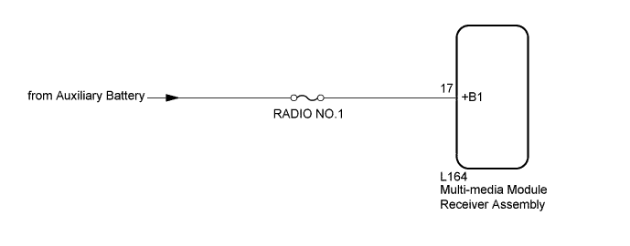
WIRING DIAGRAM
INSPECTION PROCEDURE
Note
Inspect the fuses for circuits related to this system before performing the following inspection procedure.
PROCEDURE
-
CHECK VEHICLE SIGNAL (OPERATION CHECK)
-
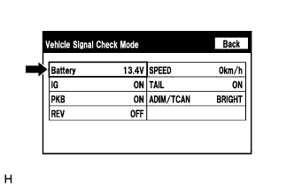
Enter the "Vehicle Signal Check Mode" screen. [Refer to Check Vehicle Signal in Operation Check Click here]
-
Check that the auxiliary battery voltage.
Standard voltage 11 to 14 V (power switch off) Tech Tips
This display is updated once per second. As a result, it is normal for the display to lag behind the actual switch operation.
NG 
CHECK HARNESS AND CONNECTOR (MULTI-MEDIA MODULE RECEIVER ASSEMBLY - BATTERY) Click here
OK 
-
-
CLEAR DTC
-
Clear the DTCs Click here.
NEXT
-
-
CHECK FOR DTC
-
Recheck for DTCs and check if the same DTC is output again Click here.
OK No DTCs are output.
NG 
REPLACE MULTI-MEDIA MODULE RECEIVER ASSEMBLY Click here
OK 
USE SIMULATION METHOD TO CHECK Click here
-
-
CHECK HARNESS AND CONNECTOR (MULTI-MEDIA MODULE RECEIVER ASSEMBLY - BATTERY)
-
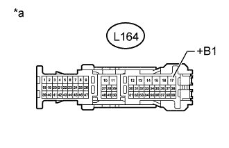
Text in Illustration *a Front view of wire harness connector
(to Multi-media Module Receiver Assembly)
Disconnect the multi-media module receiver assembly connector.
-
Measure the voltage according to the value(s) in the table below.
Standard Voltage Tester Connection Switch Condition Specified Condition L164-17 (+B1) - Body ground Power switch off 11 to 14 V
NG
REPAIR OR REPLACE HARNESS OR CONNECTOR
OK
REPLACE MULTI-MEDIA MODULE RECEIVER ASSEMBLY Click here
-