AUDIO AND VISUAL SYSTEM TERMINALS OF ECU

-
MULTI-MEDIA MODULE RECEIVER ASSEMBLY
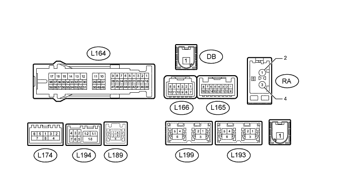
Terminal No. (Symbol) Wiring Color Terminal Description Condition Specified Condition L166-7 (GND2) - L164-12 (GND1) G - W-B Ground Always Below 1 Ω L166-11 (ACC) - L164-12 (GND1) V - W-B Power source (ACC) Power switch on (ACC) 11 to 14 V Power switch off Below 1 V L166-12 (+B) - L164-12 (GND1) R - W-B Power source (+B) Power switch off 11 to 14 V L164-1 (CANH) R CAN communication signal - - L164-2 (CANL) G CAN communication signal - - L164-3 (CNH1) W Local bus communication signal - - L164-4 (CNL1) B Local bus communication signal - - L164-9 (VMTR) - L164-12 (GND1)*1 BE - W-B Mute signal RES playing → Source changed 2 V or higher → Below 0.7 V → 2 V or higher L164-10 (VMTF) - L164-12 (GND1) R - W-B Visual mute signal When image on display switches 3.5 V or higher → Below 1 V → 3.5 V or higher L164-12 (GND1) - Body ground W-B - Body ground Ground Always Below 1 Ω L164-13 (ILL-) - L164-12 (GND1) LG - W-B Illumination signal Power switch on (IG), light control switch off → tail or head (Light intensity is not max. or min.) Below 1 V → Pulse generation L164-14 (ILL+) - L164-12 (GND1) G - W-B Illumination signal Power switch on (IG), light control switch off → tail or head position Below 1 V → 11 to 14 V L164-15 (IG) - L164-12 (GND1) V - W-B Power source (IG) Power switch on (IG) 11 to 14 V Power switch off Below 1 V L164-16 (ACC1) - L164-12 (GND1) LG - W-B Power source (ACC) Power switch on (ACC) 11 to 14 V Power switch off Below 1 V L164-17 (+B1) - L164-12 (GND1) R - W-B Power source Always 11 to 14 V L164-27 (MIN+) - L164-12 (GND1) Y - W-B*1
W - W-B*2
Microphone voice signal See "Microphone & Voice Recognition Check" in Operation Check Click here
- L164-28 (SGND) - L164-12 (GND1) Shielded - W-B Shielded ground Always Below 1 Ω L164-29 (MACC) - L164-12 (GND1)*2 B - W-B Telephone microphone assembly power supply Power switch off Below 1 V Power switch on (ACC) 4 to 6 V L164-30 (SW1) - L164-32 (SWG) BR - B Steering pad switch signal Steering pad switch not operated 4.44 to 5.43 V Seek+ switch pushed 0.45 to 0.65 V Seek- switch pushed 1.19 to 1.49 V Vol+ switch pushed 2.09 to 2.54 V Vol- switch pushed 3.2 to 3.88 V L164-31 (SW2) - L164-32 (SWG) G - B Steering pad switch signal Steering pad switch not operated 4.44 to 5.43 V MODE switch pushed 0.45 to 0.65 V On hook switch pushed 1.19 to 1.49 V Off hook switch pushed 2.09 to 2.54 V Voice switch pushed 3.2 to 3.88 V L164-32 (SWG) - Body ground B - Body ground Steering pad switch signal Always Below 1 V L164-45 (TX3+) G AVC-LAN communication signal - - L164-46 (TX3-) R AVC-LAN communication signal - - L164-48 (MIN-) - L164-12 (GND1) BR - W-B*1
R - W-B*2
Microphone voice signal See "Microphone & Voice Recognition Check" in Operation Check Click here
- L164-49 (SNS2) - L164-12 (GND1) BE - W-B Microphone connection detection signal Always Below 1 V L164-56 (SPD) - L164-12 (GND1) V - W-B Speed signal from combination meter assembly See "Vehicle Signal Check Mode" in Operation Check Click here
- L165-5 (AGND) - Body ground Shielded - Body ground Shielded ground Always Below 1 Ω L165-6 (VV+) - L164-12 (GND1) R - W-B Video signal External device playing (When stereo jack used) A waveform synchronized with sound is output L165-7 (VAR+) - L165-15 (VA-) W - R Sound signal (Right) AUX audio device playing (When No. 1 stereo jack adapter used) A waveform synchronized with sound is output. L165-8 (VAL+) - L165-15 (VA-) B - R Sound signal (Left) AUX audio device playing (When No. 1 stereo jack adapter used) A waveform synchronized with sound is output. L165-13 (SG) - L164-12 (GND1) Shield - W-B Shield ground Always Below 1 V L165-14 (VV-) - L164-12 (GND1) G - W-B Video signal External device playing (When stereo jack used) A waveform synchronized with sound is output L165-15 (VA-) - L164-12 (GND1) R - W-B Sound signal ground Always Below 1 V L165-16 (ADPG) - L164-12 (GND1) BR - W-B External device connector detection signal External device connected Below 1 V External device not connected 2.1 to 3 V L174-1 (WUO) - L164-12 (GND1) W - W-B MOST communication signal Power switch on (ACC) 4.5 V or higher Power switch off Below 1 V L174-2 (MI+) B MOST communication signal - - L174-3 (MI-) B MOST communication signal - - L174-4 (SLDI) - Body ground Shielded - Body ground Shielded ground Always Below 1 Ω L174-5 (MO+) B MOST communication signal - - L174-6 (MO-) B MOST communication signal - - L174-7 (SLDO) - Body ground Shielded - Body ground Shielded ground Always Below 1 Ω L189-1 (USV1) # Power source - - L189-2 (US1-) # Data signal - - L189-3 (US1+) # Data signal - - L189-4 (UGD1) # Ground - - L189-5 (USG1) Shielded Shielded ground - - L194-1-1 (USB-)*1 B USB communication line - - L194-1-2 (USB+)*1 B USB communication line - - L194-1-3 (USBS) - Body ground*1 B - Body ground Shielded ground Always Below 1 Ω L194-2 (USBG) - Body ground*1 W - Body ground Shielded ground Always Below 1 Ω L194-3 (VOT+) - L164-12 (GND1)*1 G - W-B Sent voice signal Destination assist service in use and vehicle occupant speaking to operator A waveform synchronized with the sent voice is output. L194-4 (USBV) - L164-12 (GND1)*1 W - W-B DCM (Telematics transceiver) power supply Power switch on (ACC) 4.75 to 5.25 V Power switch off Below 1 V L194-5 (VOT-) - L164-12 (GND1)*1 B - W-B Sent voice signal Destination assist service in use and vehicle occupant speaking to operator A waveform synchronized with the sent voice is output. L194-6 (VOR-) - L164-12 (GND1)*1 R - W-B Receive voice signal Destination assist service in use and operator speaking to vehicle occupant A waveform synchronized with the received voice is output. L194-7 (VOR+) - L164-12 (GND1)*1 W - W-B Receive voice signal Destination assist service in use and operator speaking to vehicle occupant A waveform synchronized with the received voice is output. L193-4 (GVO+)*3 # GVIF cable signal - - L193-5 (GVO-)*3 # GVIF cable signal - - L193-6 (GVG2)*3 # Shielded ground - - L199-1 (GVI+) # GVIF cable signal - - L199-2 (GVI-) # GVIF cable signal - - L199-3 (GVG1) # Shielded ground - -
-
*1: w/ Telematics Transceiver
-
*2: w/o Telematics Transceiver
-
*3: w/ Rear Seat Entertainment System
-
-
STEREO COMPONENT AMPLIFIER ASSEMBLY

Terminal No. (Symbol) Wiring Color Terminal Description Condition Specification R96-1 (SL+) - R95-3 (GND) B - W-B Sound signal (Rear Left) Audio system playing A waveform synchronized with sound is output. R96-2 (SR+) - R95-3 (GND) B - W-B Sound signal (Rear Right) Audio system playing A waveform synchronized with sound is output. R96-3 (RL+) - R95-3 (GND) P - W-B Sound signal (Rear Left) Audio system playing A waveform synchronized with sound is output. R96-4 (RR+) - R95-3 (GND) W - W-B Sound signal (Rear Right) Audio system playing A waveform synchronized with sound is output. R96-5 (SL-) - R95-3 (GND) Y - W-B Sound signal (Rear Left) Audio system playing A waveform synchronized with sound is output. R96-6 (SR-) - R95-3 (GND) Y - W-B Sound signal (Rear Right) Audio system playing A waveform synchronized with sound is output. R96-9 (RL-) - R95-3 (GND) Y - W-B Sound signal (Rear Left) Audio system playing A waveform synchronized with sound is output. R96-10 (RR-) - R95-3 (GND) R - W-B Sound signal (Rear Right) Audio system playing A waveform synchronized with sound is output. R95-1 (+B) - R95-3 (GND) GR - W-B Power source (+B) Always 11 to 14 V R95-2 (TMUT) - R95-3 (GND)* SB - W-B Mute signal Audio system playing Above 3.5 V Emergency call mode Below 1 V R95-3 (GND) - Body ground W-B - Body ground Ground Always Below 1 Ω R95-4 (WFL+) - R95-3 (GND) Y - W-B Sound signal (Front Left) Audio system playing A waveform synchronized with sound is output. R95-5 (WFR+) - R95-3 (GND) B - W-B Sound signal (Front Right) Audio system playing A waveform synchronized with sound is output. R95-6 (WF1+) - R95-3 (GND) B - W-B Sound signal (Woofer) Audio system playing A waveform synchronized with sound is output. R95-7 (CTR+) - R95-3 (GND) P - W-B Sound signal (Front Center) Audio system playing A waveform synchronized with sound is output. R95-12 (FL+) - R95-3 (GND) L - W-B Sound signal (Front Left) Audio system playing A waveform synchronized with sound is output. R95-13 (FR+) - R95-3 (GND) B - W-B Sound signal (Front Right) Audio system playing A waveform synchronized with sound is output. R95-14 (TWL+) - R95-3 (GND) W - W-B Sound signal (Rear Left) Audio system playing A waveform synchronized with sound is output. R95-15 (TWR+) - R95-3 (GND) V - W-B Sound signal (Rear Right) Audio system playing A waveform synchronized with sound is output. R95-16 (+B2) - R95-3 (GND) B - W-B Power source Always 11 to 14 V R95-17 (SPD) - R95-3 (GND) V - W-B Vehicle speed signal Power switch on (IG)
Wheel being rotated
Pulse generation R95-18 (GND2) - Body ground W-B - Body ground Ground Always Below 1 Ω R95-19 (WFL-) - R95-3 (GND) B - W-B Sound signal (Front Left) Audio system playing A waveform synchronized with sound is output. R95-20 (WFR-) - R95-3 (GND) Y - W-B Sound signal (Front Right) Audio system playing A waveform synchronized with sound is output. R95-21 (WF1-) - R95-3 (GND) Y - W-B Sound signal (Woofer) Audio system playing A waveform synchronized with sound is output. R95-22 (CTR-) - R95-3 (GND) V - W-B Sound signal (Front Center) Audio system playing A waveform synchronized with sound is output. R95-27 (FL-) - R95-3 (GND) LG - W-B Sound signal (Front Left) Audio system playing A waveform synchronized with sound is output. R95-28 (FR-) - R95-3 (GND) Y - W-B Sound signal (Front Right) Audio system playing A waveform synchronized with sound is output. R95-29 (TWL-) - R95-3 (GND) R - W-B Sound signal (Rear Left) Audio system playing A waveform synchronized with sound is output. R95-30 (TWR-) - R95-3 (GND) P - W-B Sound signal (Rear Right) Audio system playing A waveform synchronized with sound is output. R108-1 (WUO) - R95-3 (GND) W - W-B MOST communication signal Power switch on (ACC) 4.5 V or higher Power switch off Below 1 V R108-2 (MI+) B MOST communication signal - - R108-3 (MI-) B MOST communication signal - - R108-4 (SLDI) - Body ground Shielded - Body ground Shielded ground Always Below 1 Ω R108-5 (MO+) B MOST communication signal - - R108-6 (MO-) B MOST communication signal - - R108-7 (SLDO) - Body ground Shielded - Body ground Shielded ground Always Below 1 Ω R108-8 (WUI) - R95-3 (GND) W - W-B MOST communication wake-up signal Power switch on (ACC) 4.5 V or higher Power switch off Below 1 V
-
*: w/ Telematics Transceiver
-
-
ACCESSORY METER ASSEMBLY
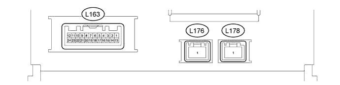
Terminal No. (Symbol) Wiring Color Terminal Description Condition Specified Condition L163-2 (ILL) - L163-13 (GND1) G - W-B Illumination signal Power switch on (IG), light control switch off Below 1 V Tail or head position 11 to 14 V L163-5 (TX2+) G AVC-LAN communication signal - - L163-6 (TX1+)* R AVC-LAN communication signal - - L163-7 (TX+) G AVC-LAN communication signal - - L163-11 (VMTI) - L163-13 (GND1) R - W-B Visual mute signal When image on display switches 3.5 V or higher → Below 1 V → 3.5 V or higher L163-12 (+B2) - L163-13 (GND1) R - W-B Power source Always 11 to 14 V L163-13 (GND1) - Body ground W-B - Body ground Ground Always Below 1 Ω L163-15 (WUI) P Local bus communication signal - - L163-16 (WUO) Y Local bus communication signal - - L163-17 (TX2-) R AVC-LAN communication signal - - L163-18 (TX1-)* BR AVC-LAN communication signal - - L163-19 (TX-) R AVC-LAN communication signal - - L163-23 (IG) - L163-13 (GND1) V - W-B Power source (IG) Power switch on (IG) 11 to 14 V Power switch off Below 1 V L163-24 (ACC) - L163-13 (GND1) LG - W-B Power source (ACC) Power switch on (ACC) 11 to 14 V Power switch off Below 1 V
-
*: w/ Audio Switch
-
-
CLOCK ASSEMBLY

Terminal No. (Symbol) Wiring Color Terminal Description Condition Specified Condition L161-2 (TX-1) R AVC-LAN communication signal - - L161-3 (TX+1) G AVC-LAN communication signal - - L161-5 (B) - L161-7 (E) R - W-B Power source Always 11 to 14 V L161-7 (E) - Body ground W-B - Body ground Ground Always Below 1 V L161-10 (ACC) - L161-7 (E) LG - W-B Power source (ACC) Power switch on (ACC) 11 to 14 V -
REMOTE TOUCH (REMOTE OPERATION BOARD) Click here
-
DCM (TELEMATICS TRANSCEIVER) (w/ Emergency Call Switch) Click here