TRIP SWITCH REMOVAL

Tech Tips
-
Use the same procedure for RHD and LHD vehicles.
-
The procedure listed below is for LHD vehicles.
-
DISABLE AUTOAWAY/RETURN FUNCTION
-
Disable the autoaway/return function by changing the customize parameter Click here.
Note
Record the current customize parameter setting (whether the autoaway/return function is enabled or disabled) in order to restore the current setting after finishing the operation.
Tech Tips
Performing the above operation causes the autoaway/return function to be disabled when the power switch is turned off.
-
Turn the power switch on (IG). Operate the tilt and telescopic switch to fully retract and tilt up the steering column assembly.
-
Turn the power switch off.
-
-
REMOVE INSTRUMENT SIDE PANEL LH
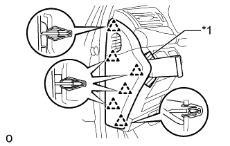
Text in Illustration *1 Protective Tape
-
Apply protective tape as shown in the illustration.
-
Using moulding remover D, detach the 6 clips and remove the instrument side panel LH.
-
-
REMOVE INSTRUMENT PANEL ORNAMENT
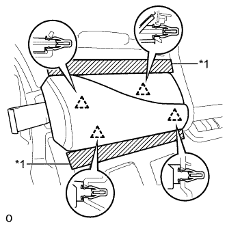
Text in Illustration *1 Protective Tape
-
Apply protective tape as shown in the illustration.
-
Using moulding remover B, detach the 4 clips and remove the instrument panel ornament.
-
Disconnect the connector.
-
-
REMOVE NO. 1 INSTRUMENT PANEL SAFETY PAD SUB-ASSEMBLY
-
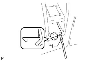
Text in Illustration *1 Protective Tape Using a screwdriver, detach the claw and remove the switch base hole cover from the No. 1 instrument panel safety pad sub-assembly.
Tech Tips
Tape the screwdriver tip before use.
-
Remove the bolt.
-
Remove the screw <C>.
-
Detach the 5 clips and claw and remove the No. 1 instrument panel safety pad sub-assembly.
-
Disconnect each connector.
-
-
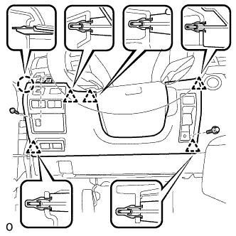
REMOVE NO. 2 INSTRUMENT CLUSTER FINISH PANEL SUB-ASSEMBLY
-
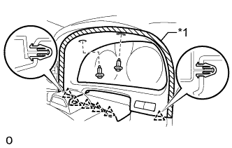
Text in Illustration *1 Protective Tape Apply protective tape to the area shown in the illustration.
-
Remove the 2 clips.
-
Detach the 6 clips and remove the instrument finish panel sub-assembly.
-
Disconnect the 2 connectors.
-
-
REMOVE TRIP SWITCH
-
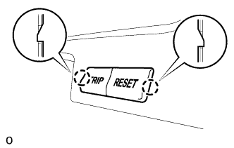
w/o Night View System:
Detach the 2 claws and remove the trip switch from the No. 2 instrument cluster finish panel sub-assembly.
-
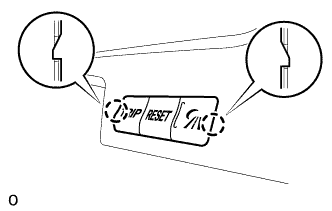
w/ Night View System:
Detach the 2 claws and remove the trip switch from the No. 2 instrument cluster finish panel sub-assembly.
-