METER / GAUGE SYSTEM, Diagnostic DTC:B1500

| DTC Code | DTC Name |
|---|---|
| B1500 | Fuel Sender Open Detected |
DESCRIPTION
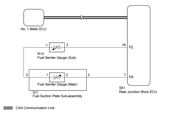
This DTC is output when the No. 1 meter ECU detects the fuel sender gauge malfunction via the CAN.
| DTC Code | DTC Detection Condition | Trouble Area |
|---|---|---|
| B1500 | When No. 1 meter ECU detects fuel sender gauge malfunction |
|
WIRING DIAGRAM
INSPECTION PROCEDURE
PROCEDURE
-
CHECK CAN COMMUNICATION SYSTEM
-
Check for DTC Click here [for LHD], Click here [for RHD]).
Result Result Proceed to CAN communication system DTC is not output A CAN communication system DTC is output (for LHD) B CAN communication system DTC is output (for RHD) C
B 
Go to CAN COMMUNICATION SYSTEM Click here
C
Go to CAN COMMUNICATION SYSTEM Click here
A 
-
-
PERFORM ACTIVE TEST USING INTELLIGENT TESTER (FUEL METER OPERATION)
-
Operate the intelligent tester according to the steps on the display and select "Active Test".
Combination Meter Tester Display Test Part Control Range Diagnostic Note Fuel Meter Operation Fuel receiver gauge EMPTY, 1/2 or FULL Perform test with vehicle stopped and engine idling OK Needle indication is normal.
NG
REPLACE NO. 1 METER ECU Click here
OK
-
-
READ VALUE USING INTELLIGENT TESTER (FUEL INPUT)
-
Operate the intelligent tester according to the display and select "Data List".
Combination Meter Tester Display Measurement Item/Range Normal Condition Diagnostic Note Fuel Input Fuel sender gauge (main) input signal/Min.: 0, Max.: 127.5 Fuel sender input value Unit: L OK Fuel value displayed on tester is almost the same as needle indication.
NG 
CHECK HARNESS AND CONNECTOR (REAR JUNCTION BLOCK ECU - FUEL SUCTION PLATE SUB-ASSEMBLY AND FUEL SENDER GAUGE [SUB]) Click here
OK 
REPLACE NO. 1 METER ECU Click here
-
-
CHECK HARNESS AND CONNECTOR (REAR JUNCTION BLOCK ECU - FUEL SUCTION PLATE SUB-ASSEMBLY AND FUEL SENDER GAUGE [SUB])
-
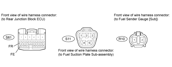
Disconnect the S61 junction block connector.
-
Disconnect the S11 suction plate connectors.
-
Disconnect the R10 gauge connectors.
-
Measure the resistance according to the value(s) in the table below.
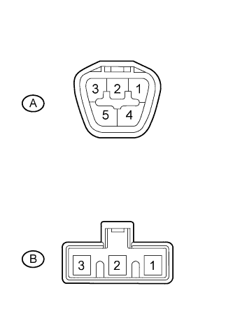
Standard resistance Tester Connector Condition Specified Condition S61-7 (FR) - S11-2 Always Below 1 Ω S61-18 (FE) - R10-2 S61-7 (FR) or S11-2 - Body ground Always 10 kΩ or higher S61-18 (FE) or R10-2 - Body ground
NG
REPAIR OR REPLACE HARNESS OR CONNECTOR
OK
-
-
CHECK HARNESS AND CONNECTOR (FUEL SUCTION PLATE SUB-ASSEMBLY - FUEL SENDER GAUGE [SUB])
-
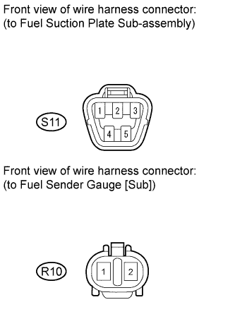
Disconnect the S11 suction plate connectors.
-
Disconnect the R10 gauge connectors.
-
Measure the resistance according to the value(s) in the table below.
Standard resistance Tester Connection Condition Specified Condition S11-3 - R10-1 Always Below 1 Ω S11-3 or R10-1 - Body ground Always 10 kΩ or higher
NG
REPAIR OR REPLACE HARNESS OR CONNECTOR
OK
-
-
INSPECT FUEL SENDER GAUGE ASSEMBLY (MAIN)
-
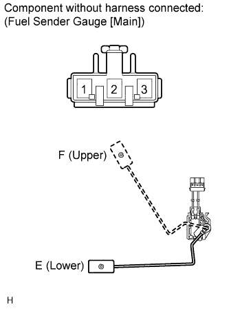
Remove the fuel sender gauge (main) Click here.
-
Measure the resistance according to the value(s) in the table below.
Standard resistance Tester Connection Condition Specified Condition 1 - 2 Float level is F (upper) 6.5 to 8.5 Ω Between float level is F (upper) and E (lower) 91.0 to 102.2 Ω Float level is E (lower) 184.8 to 188.8 Ω
NG
REPLACE FUEL SENDER GAUGE ASSEMBLY (MAIN) Click here
OK
-
-
INSPECT FUEL SUCTION PLATE SUB-ASSEMBLY
-
Remove the fuel suction plate sub-assembly Click here.
-
Measure the resistance according to the value(s) in the table below.
Standard resistance Tester Connection Condition Specified Condition A-2 - B-2 Always Below 1 Ω A-3 - B-1
NG
REPLACE FUEL SUCTION PLATE SUB-ASSEMBLY Click here
OK
-
-
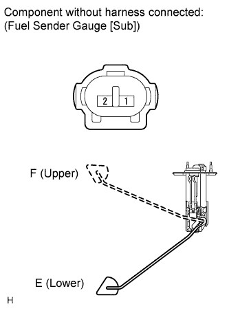
INSPECT FUEL SENDER GAUGE ASSEMBLY (SUB)
-
Remove the fuel sender gauge (sub) Click here.
-
Measure the resistance according to the value(s) in the table below.
Standard resistance Tester Connection Condition Specified Condition 1 - 2 Float level is F (upper) 6.5 to 8.5 Ω Between float level is F (upper) and E (lower) 112.7 to 125.7 Ω Float level is E (lower) 220.7 to 225.7 Ω
NG
REPLACE FUEL SENDER GAUGE ASSEMBLY (SUB) Click here
OK
-
-
REPLACE NO. 1 METER ECU
-
Temporarily replace the No. 1 meter ECU with a new one Click here.
NEXT
-
-
CHECK NO. 1 METER ECU (FUEL RECEIVER GAUGE)
-
Check that the operation of the fuel sender gauge in the meter returns to normal Click here.
OK Operation of the fuel sender gauge returns to normal.
NG
REPLACE LUGGAGE ROOM JUNCTION BLOCK ASSEMBLY (REAR JUNCTION BLOCK ECU)
OK
END (NO. 1 METER ECU IS DEFECTIVE)
-