ENTRY LOCK AND UNLOCK SWITCH (for Front) INSTALLATION

Tech Tips
-
Use the same procedure for the RH and LH sides.
-
The procedure listed below is for the LH side.
-
INSTALL FRONT OUTSIDE DOOR HANDLE ASSEMBLY LH
-
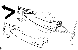
Pull and hold the bellcrank lever of the front door outside handle assembly LH as shown in the illustration.
-
Install the front door outside handle assembly LH by pushing it in the direction of the arrow in the illustration.
Note
If the bellcrank lever is not pulled and held when installing the handle, the bellcrank lever will interfere with the handle and become damaged.
-
Using a T30 ''TORX'' socket, install the screw.
-
Connect the connector.
-
-
INSTALL FRONT DOOR OUTSIDE HANDLE COVER LH
-
Using a T30 ''TORX'' socket, install the front door outside handle cover LH (with the door key cylinder) with the screw.
- Torque:
- 4.0 N*m { 41 kgf*cm, 35 in.*lbf }
-
Install the hole plug.
-
-
INSTALL FRONT DOOR GLASS SUB-ASSEMBLY LH
-
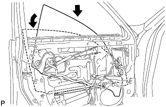
Insert the front door glass sub-assembly LH into the door panel along the glass run as indicated by the arrows in the illustration.
Note
Be careful not to damage the glass.
-
Install the front door glass sub-assembly LH to the front door window regulator sub-assembly LH with the 2 bolts.
- Torque:
- 5.5 N*m { 56 kgf*cm, 49 in.*lbf }
-
Install the hole plug.
-
-
INSTALL FRONT INNER DOOR GLASS WEATHERSTRIP LH
-
Install the front door glass weatherstrip inner LH.
-
-
INSTALL FRONT DOOR SERVICE HOLE COVER LH
-
Apply new butyl tape to the door.
-
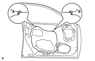
Text in Illustration *a Reference Point Install a new front door service hole cover LH using the reference points on the front door panel.
Tech Tips
-
When installing the service hole cover, pull the links and connectors through the service hole cover.
-
There should be no wrinkles or folds after attaching the service hole cover.
-
After attaching the service hole cover, check the sealing quality.
-
-
-
INSTALL FRONT DOOR TRIM BOARD SUB-ASSEMBLY LH
-
Connect the connector.
-
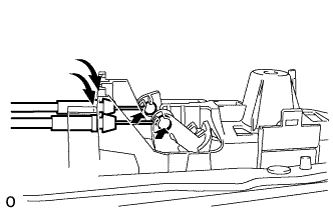
Connect the 2 cables to the inside handle.
-
Attach the 13 clips to install the front door trim board sub-assembly LH.
-
Install the 3 screws.
-
-
INSTALL POWER WINDOW REGULATOR MASTER SWITCH ASSEMBLY LH
-
Connect the connector.
-
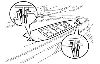
Attach the 2 claws to install the power window regulator master switch assembly with front door armrest base panel.
-
-
INSTALL FRONT DOOR INSIDE HANDLE BEZEL PLUG LH
-
Attach the 3 claws to install the front door inside handle bezel plug LH.
-
-
CONNECT CABLE TO AUXILIARY BATTERY NEGATIVE TERMINAL
Note
When disconnecting the cable, some systems need to be initialized after the cable is reconnected Click here.
-
INSTALL BATTERY SERVICE HOLE COVER LH
-

Text in Illustration *A for Standard *B for Ottoman Attach the battery service hole cover LH with the clip and fastening tape.
-
-
INSTALL DECK TRIM SIDE BOARD LH (w/o Spare Tire)
-

Attach the 2 clips to install the deck trim side board LH.
-
-
INSTALL DECK BOARD ASSEMBLY (w/o Spare Tire)

-
INSTALL LUGGAGE COMPARTMENT MAT SUB-ASSEMBLY (w/ Spare Tire)
