COMBINATION METER REMOVAL

CAUTION:
Do not touch any parts of the circuit of the meter display panel and condenser. Even if the power switch is off, the meter display panel and condenser are electrically charged.
Note
-
Make sure the combination meter glass does not become dirty with fingerprints, oil, etc. If dirty, clean with a soft cloth.
-
Be careful of static electricity when handling the combination meter. Make sure the work area has static electricity prevention measures.
Tech Tips
-
Use the same procedure for RHD and LHD vehicles.
-
The procedure listed below is for LHD vehicles.
-
REMOVE LUGGAGE COMPARTMENT MAT SUB-ASSEMBLY (w/ Spare Tire)

-
REMOVE DECK BOARD ASSEMBLY (w/o Spare Tire)

-
REMOVE DECK TRIM SIDE BOARD LH (w/o Spare Tire)
-

Detach the 2 clips and remove the deck trim side board LH.
-
-
REMOVE BATTERY SERVICE HOLE COVER LH
-

Text in Illustration *A for Standard *B for Ottoman *1 Fastening Tape Detach the clip, fastening tape and remove the battery service hole cover LH.
-
-
PRECAUTION
Note
After turning the power switch off, waiting time may be required before disconnecting the cable from the auxiliary battery negative (-) terminal. Therefore, make sure to read the disconnecting the cable from the auxiliary battery negative (-) terminal notices before proceeding with work Click here.
-
DISABLE AUTOAWAY/RETURN FUNCTION
-
Disable the autoaway/return function by changing the customize parameter Click here.
Note
Record the current customize parameter setting (whether the autoaway/return function is enabled or disabled) in order to restore the current setting after finishing the operation.
Tech Tips
Performing the above operation causes the autoaway/return function to be disabled when the power switch is turned off.
-
Turn the power switch on (IG). Operate the tilt and telescopic switch to fully retract and tilt up the steering column assembly.
-
Turn the power switch off.
-
-
DISCONNECT CABLE FROM AUXILIARY BATTERY NEGATIVE TERMINAL
-
Disconnect the cable from the auxiliary battery negative (-) terminal.
CAUTION:
Wait at least 90 seconds after disconnecting the cable from the auxiliary negative (-) battery terminal to disable the SRS system.
Note
When disconnecting the cable, some systems need to be initialized after the cable is reconnected Click here.
-
-
REMOVE INSTRUMENT SIDE PANEL LH
Text in Illustration *1 Protective Tape
-
Apply protective tape as shown in the illustration.
-
Using moulding remover D, detach the 6 clips and remove the instrument side panel LH.
-
-
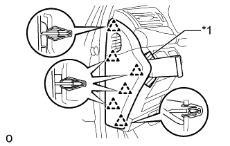
REMOVE INSTRUMENT PANEL ORNAMENT
Text in Illustration *1 Protective Tape
-
Apply protective tape as shown in the illustration.
-
Using moulding remover B, detach the 4 clips and remove the instrument panel ornament.
-
Disconnect the connector.
-
-
REMOVE NO. 1 INSTRUMENT PANEL SAFETY PAD SUB-ASSEMBLY
-
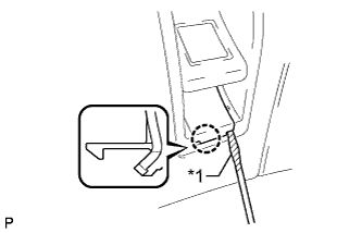
Text in Illustration *1 Protective Tape Using a screwdriver, detach the claw and remove the switch base hole cover from the No. 1 instrument panel safety pad sub-assembly.
Tech Tips
Tape the screwdriver tip before use.
-
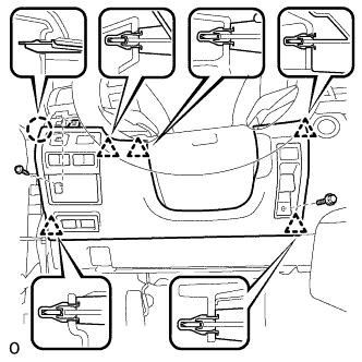
Remove the bolt.
-
Remove the screw <C>.
-
Detach the 5 clips and claw and remove the No. 1 instrument panel safety pad sub-assembly.
-
Disconnect each connector.
-
-
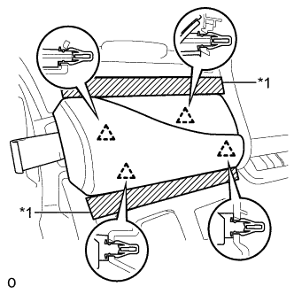
REMOVE NO. 2 INSTRUMENT CLUSTER FINISH PANEL SUB-ASSEMBLY
-
Text in Illustration *1 Protective Tape Apply protective tape to the area shown in the illustration.
-
Remove the 2 clips.
-
Detach the 6 clips and remove the instrument finish panel sub-assembly.
-
Disconnect the 2 connectors.
-
-
REMOVE STEERING COLUMN COVER (w/o Driver Monitor Camera)
-
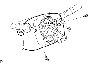
Remove the 3 screws.
-
Detach the 2 claws to remove the steering column cover lower.
Note
Do not damage the tilt and telescopic switch.
-
Detach the 4 clips.
-
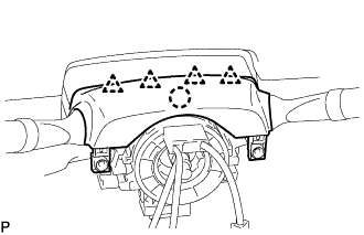
Detach the claw to remove the upper steering column cover.
-
-
REMOVE STEERING COLUMN COVER (w/ Driver Monitor Camera)
-

Remove the 3 screws.
-
Detach the 2 claws to remove the lower steering column cover.
Note
Do not damage the tilt and telescopic switch.
-
Detach the 4 clips.
-
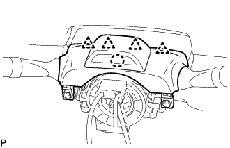
Detach the claw and remove the upper steering column cover.
Note
Do not damage the tilt and telescopic switch.
-
Disconnect the driver monitor connector.
-
-
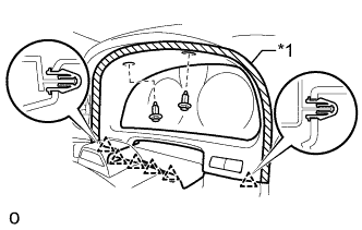
REMOVE COMBINATION METER ASSEMBLY
-
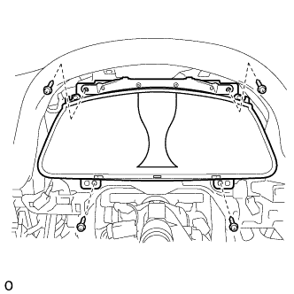
Remove the 4 screws and combination meter assembly.
-
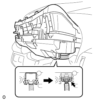
Detach the 2 claws and open the connector cover.
-
Disconnect the connector.
-