LANE-KEEPING ASSIST SYSTEM TERMINALS OF ECU

-
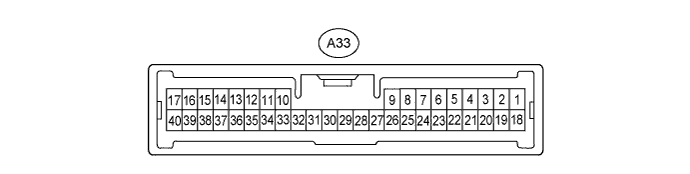
CHECK DRIVING SUPPORT ECU
-
Disconnect the A33 ECU connector.
-
Measure the voltage and resistance according to the value(s) in the table below.
Terminal No. (Symbol) Wiring Color Terminal Description Condition Specified Condition A33-13 (B) - Body ground Y - Body ground Power supply Always 11 to 14 V A33-25 (GND) - Body ground W-B - Body ground Ground Always Below 1 Ω A33-11 (STP-) - Body ground BE - Body ground Stop light switch signal input Depress brake pedal 7.5 to 14 V Release brake pedal Below 1 V A33-34 (ST1-) - Body ground G - Body ground Stop light switch signal input Power switch ON (IG), release brake pedal 7.5 to 14 V Power switch ON (IG), depress brake pedal Below 1 V If the result is not as specified, there may be a malfunction on the wire harness side.
-
-
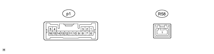
CHECK OBJECT RECOGNITION ECU
-
Disconnect the p1 ECU connector.
-
Measure the voltage and resistance according to the value(s) in the table below.
Terminal No. (Symbol) Wiring Color Terminal Description Condition Specified Condition p1-6 (IG) - Body ground V - Body ground IG power supply Power switch ON (IG) 11 to 14 V Power switch OFF Below 1 V p1-10 (GND) - Body ground W-B - Body ground Body ground Always Below 1 Ω If the result is not as specified, there may be a malfunction on the wire harness side.
-