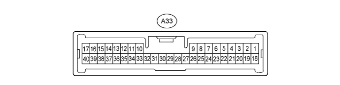
DYNAMIC RADAR CRUISE CONTROL SYSTEM TERMINALS OF ECU

-
CHECK DRIVING SUPPORT ECU
-
Disconnect the A33 ECU connector.
-
Measure the voltage and resistance according to the value(s) in the table below.
Terminal No. (Symbol) Wiring Color Terminal Description Condition Specified Condition A33-11 (STP-) - Body ground BE - Body ground Stop light switch signal input Depress brake pedal 7.5 to 14 V A33-11 (STP-) - Body ground BE - Body ground Stop light switch signal input Release brake pedal Below 1 V A33-13 (B) - Body ground Y - Body ground Power supply Power switch ON (IG) 7.5 to 14 V A33-13 (B) - Body ground Y - Body ground Power supply Power switch OFF Below 1 V A33-25 (GND) - Body ground W-B - Body ground Body ground Always Below 1 Ω A33-27 (CCS) - Body ground V - Body ground Cruise control main switch signal Cruise control switch ON Below 2.5 Ω A33-27 (CCS) - Body ground V - Body ground Cruise control main switch signal Cruise control switch OFF 1MΩ or higher A33-27 (CCS) - Body ground V - Body ground Cruise control main switch signal +RES switch is held ON 235 to 245 Ω A33-27 (CCS) - Body ground V - Body ground Cruise control main switch signal -SET switch is held ON 617 to 643 Ω A33-27 (CCS) - Body ground V - Body ground Cruise control main switch signal CANCEL switch is held ON 1509 to 1571 Ω A33-30 (CCHG) - Body ground LG - Body ground Distance control switch signal Cruise control switch ON, MODE switch ON Below 2.5 Ω A33-30 (CCHG) - Body ground LG - Body ground Distance control switch signal Cruise control switch ON, MODE switch OFF 1MΩ or higher A33-34 (ST1-) - Body ground G - Body ground Stop light switch signal input Power switch ON (IG),
release brake pedal
7.5 to 14 V A33-34 (ST1-) - Body ground G - Body ground Stop light switch signal input Power switch ON (IG),
depress brake pedal
Below 1 V
-