ENGINE IMMOBILISER SYSTEM TERMINALS OF ECU

-
CHECK POWER SWITCH

-
Disconnect the L36 switch connector.
-
Measure the resistance of the wire harness.
Terminal No. (Symbols) Wiring Color Terminal Description Condition Specified Condition L36-5 (GND) - Body ground W - Body ground Ground Always Below 1 Ω
-
If the result is not as specified, there may be a malfunction on the wire harness side.
-
-
Reconnect the L36 switch connector.
-
Measure the resistance and voltage of the connector.
Terminal No. (Symbols) Wiring Color Terminal Description Condition Specified Condition L36-8 (AGND) - Body ground L - Body ground Ground Always Below 1 Ω L36-14 (VC5) - L36-8 (AGND) V - L Power supply Key is not in cabin Below 1 V Power switch is pressed* 4.6 to 5.4 V L36-10 (CODE) - L36-8 (AGND) W - L Demodulated signal of key code data Key is not in cabin Below 1 V Power switch is pressed and key is held close to power switch* Pulse generation (see waveform 1) L36-9 (TXCT) - L36-8 (AGND) BE - L Key code output signal Key is not in cabin Below 1 V Power switch is pressed and key is held close to power switch* Pulse generation (see waveform 2) Tech Tips
*: Remove the key's battery before performing this inspection.
-
If the result is not as specified, the switch may have a malfunction.
-
-
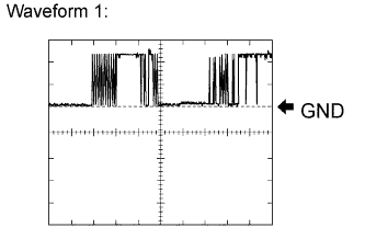
Using an oscilloscope, check waveform 1.
Waveform 1 (Reference): Item Content Terminal No. (Symbols) L36-10 (CODE) - L36-8 (AGND) Tool Setting 2 V/DIV., 20 msec./DIV. Condition Power switch is pressed and key is held close to power switch* Tech Tips
*: Remove the key's battery before performing this inspection.
-
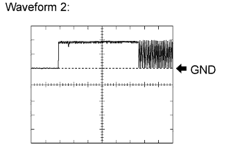
Using an oscilloscope, check waveform 2.
Waveform 2 (Reference): Item Content Terminal No. (Symbols) L36-9 (TXCT) - L36-8 (AGND) Tool Setting 2 V/DIV., 20 msec./DIV. Condition Power switch is pressed and key is held close to power switch* Tech Tips
*: Remove the key's battery before performing this inspection.
-
-
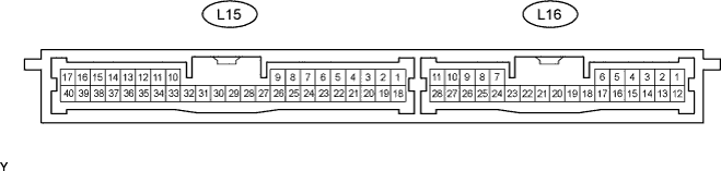
CHECK CERTIFICATION ECU
-
Disconnect the L15 ECU connector.
-
Measure the resistance and voltage of the wire harness side connector.
Terminal No. (Symbols) Wiring Color Terminal Description Condition Specified Condition L15-17 (E) - Body ground W-B - Body ground Ground Always Below 1 Ω L15-1 (+B1) - L15-17 (E) L - W-B +B power supply Always 11 to 14 V L15-18 (IG) - L15-17 (E) L - W-B Ignition power supply Power switch OFF Below 1 V
-
If the result is not as specified, there may be a malfunction on the wire harness side.
-
-
Reconnect the L15 ECU connector.
-
Measure the resistance and voltage of the connector.
Terminal No. (Symbols) Wiring Color Terminal Description Condition Specified Condition L15-40 (AGND) - Body ground L - Body ground Power switch ground Always Below 1 Ω L15-30 (VC5) - L15-40 (AGND) V - L Power switch power supply Key is not in cabin Below 1 V Power switch is pressed* 4.6 to 5.4 V L15-9 (CODE) - L15-40 (AGND) W - L Power switch CODE input Key is not in cabin Below 1 V Power switch is pressed and key is held close to power switch* Pulse generation (see waveform 1) L15-8 (TXCT) - L15-40 (AGND) BE - L Power switch TX output Key is not in cabin Below 1 V Power switch is pressed and key is held close to power switch* Pulse generation (see waveform 2) Tech Tips
*: Remove the key's battery before performing this inspection.
-
If the result is not as specified, the ECU may have a malfunction.
-
-
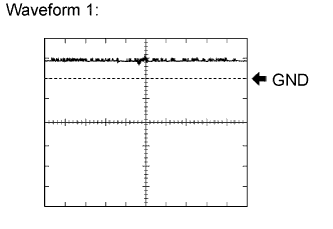
Using an oscilloscope, check waveform 1.
Waveform 1 (Reference): Item Content Terminal No. (Symbols) L15-9 (CODE) - L15-40 (AGND) Tool Setting 2 V/DIV., 20 msec./DIV. Condition Power switch is pressed and key is held close to power switch* Tech Tips
*: Remove the key's battery before performing this inspection.
-
Using an oscilloscope, check waveform 2.
Waveform 2 (Reference): Item Content Terminal No. (Symbols) L15-8 (TXCT) - L15-40 (AGND) Tool Setting 2 V/DIV., 20 msec./DIV. Condition Power switch is pressed and key is held close to power switch* Tech Tips
*: Remove the key's battery before performing this inspection.
-
-
CHECK ID CODE BOX

-
Disconnect the L32 box connector.
-
Measure the resistance and voltage of the wire harness side connector.
Terminal No. (Symbols) Wiring Color Terminal Description Condition Specified Condition L32-8 (GND) - Body ground W-B*1 - Body ground
B*2 - Body ground
Ground Always Below 1 Ω L32-1 (+B) - L32-8 (GND) L - W-B*1
L - B*2
+B power supply Always 11 to 14 V Tech Tips
*1: for LHD
*2: for RHD
-
If the result is not as specified, there may be a malfunction on the wire harness side.
-
-
Reconnect the L32 box connector.
-
Measure the voltage of the connector.
Terminal No. (Symbols) Wiring Color Terminal Description Condition Specified Condition L32-5 (EFII) - L32-8 (GND) B - W-B*1
B - B*2
Hybrid vehicle control ECU input signal Power switch OFF Below 1 V Power switch ON (IG) Pulse generation (see waveform 1) L32-6 (EFIO) - L32-8 (GND) L - W-B*1
L - B*2
Hybrid vehicle control ECU output signal Power switch OFF Below 1 V Power switch ON (IG) Pulse generation (see waveform 2) Tech Tips
*1: for LHD
*2: for RHD
-
If the result is not as specified, the box may have a malfunction.
-
-
Using an oscilloscope, check waveform 1.
Waveform 1 (Reference): Item Content Terminal No. (Symbols) L32-5 (EFII) - L32-8 (GND) Tool Setting 10 V/DIV., 100 msec./DIV. Condition Power switch ON (IG) -
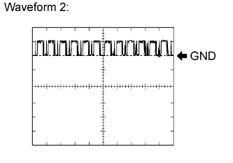
Using an oscilloscope, check waveform 2.
Waveform 2 (Reference): Item Content Terminal No. (Symbols) L32-6 (EFIO) - L32-8 (GND) Tool Setting 10 V/DIV., 100 msec./DIV. Condition Power switch ON (IG)
-
-
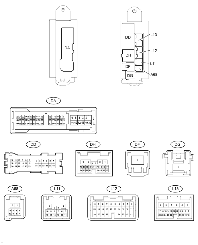
CHECK MAIN BODY ECU (DRIVER SIDE JUNCTION BLOCK)
-
Disconnect the DA and DF ECU connectors.
-
Measure the resistance and voltage according to the value(s) in the table below.
Terminal No. (Symbols) Wiring Color Terminal Description Condition Specified Condition DA-40 (GND2) - Body ground W-B - Body ground Ground Always Below 1 Ω DA-41 (GND2) - Body ground W-B - Body ground Ground Always Below 1 Ω DF-1 (ACC) - DA-40 (GND2) B - W-B ACC power supply Power switch OFF Below 1 V Power switch ON (ACC) 11 to 14 V DF-1 (IG) - DA-40 (GND2) B - W-B IG power supply Power switch OFF Below 1 V Power switch ON (IG) 11 to 14 V
-
If the result is not as specified, there may be a malfunction on the wire harness side.
-
-
-
CHECK STEERING LOCK ACTUATOR (STEERING LOCK ECU)

-
Disconnect the L33 ECU connector.
-
Measure the resistance and voltage according to the value(s) in the table below.
Terminal No. (Symbols) Wiring Color Terminal Description Condition Specified Condition L33-2 (SGND) - Body ground BR - Body ground Ground Always Below 1 Ω L33-1 (GND) - Body ground W-B - Body ground Ground Always Below 1 Ω L33-7 (B) - Body ground P - Body ground +B power supply Always 11 to 14 V L33-6 (IG2) - Body ground L - Body ground Ignition power supply Power switch OFF Below 1 V Power switch ON (IG) 11 to 14 V
-
If the result is not as specified, there may be a malfunction on the wire harness side.
-
-
-
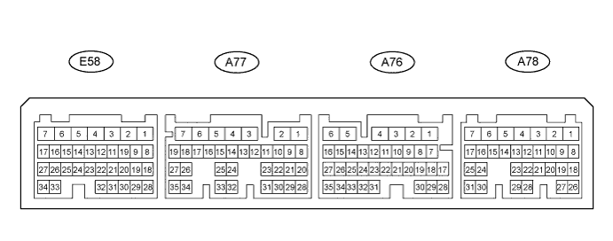
CHECK HYBRID VEHICLE CONTROL ECU
-
Measure the resistance and voltage according to the value(s) in the table below.
Terminal No. (Symbols) Wiring Color Terminal Description Condition Specified Condition A77-7 (E1) - Body ground W-B - Body ground Ground Always Below 1 Ω A77-6 (E12) - Body ground W-B - Body ground Ground Always Below 1 Ω E58-6 (GND2) - Body ground W-B - Body ground Ground Always Below 1 Ω E58-7 (GND1) - Body ground W-B - Body ground Ground Always Below 1 Ω A76-1 (BATT) - A77-7 (E1) B-W - W-B Battery (for measuring battery voltage and for hybrid vehicle control ECU memory) Always 11 to 14 V A78-1 (+B1) - A77-7 (E1) B - W-B Power source of hybrid vehicle control ECU Power switch OFF Below 1 V Power switch ON (IG) 11 to 14 V A78-2 (+B2) - A77-7 (E1) L - W-B Power source of hybrid vehicle control ECU Power switch OFF Below 1 V Power switch ON (IG) 11 to 14 V A77-32 (IMI) - A77-7 (E1) L - W-B ID code box input signal Power switch OFF Below 1 V Power switch ON (IG) Pulse generation (see waveform 1) A77-33 (IMO) - A77-7 (E1) B - W-B ID code box output signal Power switch OFF Below 1 V Power switch ON (IG) Pulse generation (see waveform 2) -
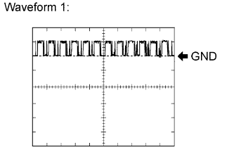
Using an oscilloscope, check waveform 1.
Waveform 1 (Reference): Item Content Terminal No. (Symbols) A77-32 (IMI) - A77-7 (E1) Tool Setting 10 V/DIV., 100 msec./DIV. Condition Power switch ON (IG) -

Using an oscilloscope, check waveform 2.
Waveform 2 (Reference): Item Content Terminal No. (Symbols) A77-33 (IMO) - A77-7 (E1) Tool Setting 10 V/DIV., 100 msec./DIV. Condition Power switch ON (IG)
-