THEFT DETERRENT SYSTEM IG Power Source Circuit
DESCRIPTION
-
When the power switch is turned ON (IG), positive (+) auxiliary battery voltage is applied to the certification ECU.
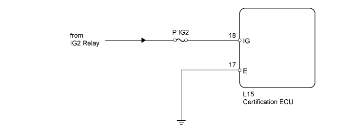
WIRING DIAGRAM
INSPECTION PROCEDURE
PROCEDURE
-
CHECK BASIC FUNCTION (ENTRY AND START FUNCTION)
-
Check the basic function of the entry and start function.
Result Result Proceed to Basic function operates normally A Basic function does not operate normally B OK Basic function operates normally.
B 
GO TO ENTRY AND START SYSTEM (for Starting) Click here
A 
-
-
INSPECT FUSE (P IG2)
-
Remove the P IG2 fuse from the passenger side junction block.
-
Measure the resistance according to the value(s) in the table below.
Standard resistance Tester connection Condition Specified Condition P IG2 fuse Always Below 1 Ω
NG
REPLACE FUSE
OK
-
-
CHECK HARNESS AND CONNECTOR (CERTIFICATION ECU - BATTERY)
-
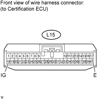
Disconnect the L15 ECU connector.
-
Measure the resistance and voltage according to the value(s) in the table below.
Standard resistance Tester Connection Condition Specified Condition L15-17 (E) - Body ground Always Below 1 Ω Standard voltage Tester Connection Switch Condition Specified Condition L15-18 (IG) - Body ground Power switch ON (IG) 11 to 14 V
NG
REPAIR OR REPLACE HARNESS OR CONNECTOR
OK 
PROCEED TO NEXT CIRCUIT INSPECTION SHOWN IN PROBLEM SYMPTOMS TABLE Click here
-