THEFT DETERRENT SYSTEM Security Indicator Light Circuit
DESCRIPTION
-
When the theft deterrent system is in the disarmed state, the security indicator will flash continuously if the immobiliser system is set, or not illuminate if the immobiliser system is not set.
When the theft deterrent system is in the armed state, the immobiliser system is automatically set and the security indicator will flash continuously.
When the theft deterrent system is in the arming preparation state and alarm sounding state, the certification ECU causes the security indicator to be illuminated.
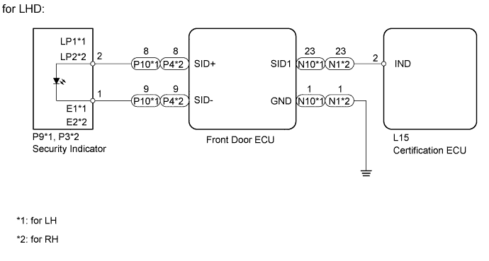
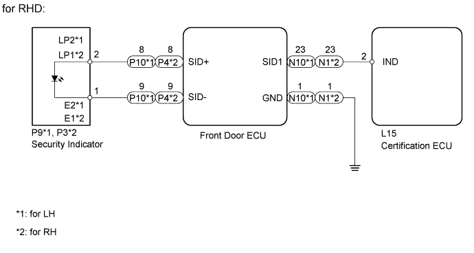
WIRING DIAGRAM
INSPECTION PROCEDURE
PROCEDURE
-
CHECK INDICATOR LIGHT ASSEMBLY
-
Check if the security indicator lights are normal.
Result Result Proceed to One security indicator light is malfunctioning A Both security indicator lights are malfunctioning B Tech Tips
If both security indicator lights are malfunctioning, there may be a malfunction in the certification ECU.
B 
REPLACE CERTIFICATION ECU
A 
-
-
PERFORM ACTIVE TEST USING INTELLIGENT TESTER (SECURITY INDICATOR)
-
Operate the intelligent tester according to the steps on the display and select "Active Test".
Entry&Start Tester Display Test Part Control Range Diagnostic Note Security Indicator Security indicator ON / OFF - OK Security indicator illuminates.
NG 
CHECK HARNESS AND CONNECTOR (DOOR ECU - SECURITY INDICATOR) Click here
OK 
REPLACE CERTIFICATION ECU
-
-
CHECK HARNESS AND CONNECTOR (DOOR ECU - SECURITY INDICATOR)
-
for LHD:
-
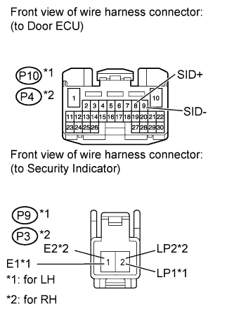
Disconnect the P10*1 or P4*2 ECU connector.
-
Disconnect the P9*1 or P3*2 indicator connector.
-
Measure the resistance according to the value(s) in the table below.
Standard resistance for LH Tester Connection Condition Specified Condition P10-8 (SID+) - P9-2 (LP1) Always Below 1 Ω P10-9 (SID-) - P9-1 (E1) Always Below 1 Ω P10-8 (SID+) or P9-2 (LP1) - Body ground Always 10 kΩ or higher P10-9 (SID-) or P9-1 (E1) - Body ground Always 10 kΩ or higher for RH Tester Connection Condition Specified Condition P4-8 (SID+) - P3-2 (LP2) Always Below 1 Ω P4-9 (SID-) - P3-1 (E2) Always Below 1 Ω P4-8 (SID+) or P3-2 (LP2) - Body ground Always 10 kΩ or higher P4-9 (SID-) or P3-1 (E2) - Body ground Always 10 kΩ or higher
-
-
for RHD:
-
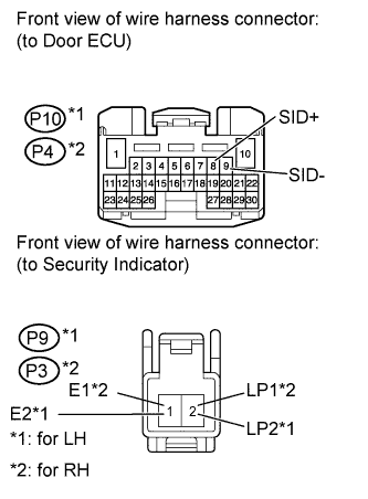
Disconnect the P10*1 or P4*2 ECU connector.
-
Disconnect the P9*1 or P3*2 indicator connector.
-
Measure the resistance according to the value(s) in the table below.
Standard resistance for LH Tester Connection Condition Specified Condition P10-8 (SID+) - P9-2 (LP2) Always Below 1 Ω P10-9 (SID-) - P9-1 (E2) Always Below 1 Ω P10-8 (SID+) or P9-2 (LP2) - Body ground Always 10 kΩ or higher P10-9 (SID-) or P9-1 (E2) - Body ground Always 10 kΩ or higher for RH Tester Connection Condition Specified Condition P4-8 (SID+) - P3-2 (LP1) Always Below 1 Ω P4-9 (SID-) - P3-1 (E1) Always Below 1 Ω P4-8 (SID+) or P3-2 (LP1) - Body ground Always 10 kΩ or higher P4-9 (SID-) or P3-1 (E1) - Body ground Always 10 kΩ or higher
-
NG
REPAIR OR REPLACE HARNESS OR CONNECTOR
OK
-
-
CHECK HARNESS AND CONNECTOR (DOOR ECU - CERTIFICATION ECU AND BODY GROUND)
-
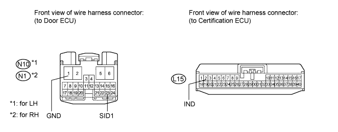
Disconnect the N10*1 or N1*2 ECU connector.
-
Disconnect the L15 ECU connector.
-
Measure the resistance according to the value(s) in the table below.
Standard resistance for LH Tester Connection Condition Specified Condition N10-23 (SID1) - L15-2 (IND) Always Below 1 Ω N10-1 (GND) - Body ground Always Below 1 Ω N10-23 (SID1) or L15-2 (IND) - Body ground Always 10 kΩ or higher for RH Tester Connection Condition Specified Condition N1-23 (SID1) - L15-2 (IND) Always Below 1 Ω N1-1 (GND) - Body ground Always Below 1 Ω N1-23 (SID1) or L15-2 (IND) - Body ground Always 10 kΩ or higher
NG
REPAIR OR REPLACE HARNESS OR CONNECTOR
OK
-
-
INSPECT INDICATOR LIGHT ASSEMBLY
-
for LHD:
-
Remove the indicator light Click here.
-
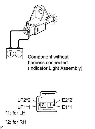
Apply battery voltage and check the operation of the indicator light.
OK Measurement Condition Specified Condition Battery positive (+) → Terminal 2 (LP1*1, LP2*2)
Battery positive (+) → Terminal 1 (E1*1, E2*2)
Illuminates Note
-
If the positive (+) lead and the negative (-) lead are incorrectly connected, the security indicator will not turn on.
-
A voltage of more than 12 V will damage the security indicator.
-
If the voltage is too low, the security indicator will not turn on.
-
-
-

for RHD:
-
Remove the indicator light Click here.
-
Apply battery voltage and check the operation of the indicator light.
OK Measurement Condition Specified Condition Battery positive (+) → Terminal 2 (LP2*1, LP1*2)
Battery positive (+) → Terminal 1 (E2*1, E1*2)
Illuminates Note
-
If the positive (+) lead and the negative (-) lead are incorrectly connected, the security indicator will not turn on.
-
A voltage of more than 12 V will damage the security indicator.
-
If the voltage is too low, the security indicator will not turn on.
-
-
NG
REPLACE INDICATOR LIGHT ASSEMBLY Click here
OK
-
-
CHECK FRONT DOOR ECU (OPERATION)
-
Temporarily replace the front door ECU with a new or normally functioning one Click here.
-
Check that the security indicator operates normally.
OK Security indicator operates normally.
NG
REPLACE CERTIFICATION ECU
OK
REPLACE FRONT DOOR ECU Click here
-