POWER SHOULDER BELT ANCHORAGE SYSTEM Front Passenger Side Seat Belt Anchor does not Operate Manually
DESCRIPTION
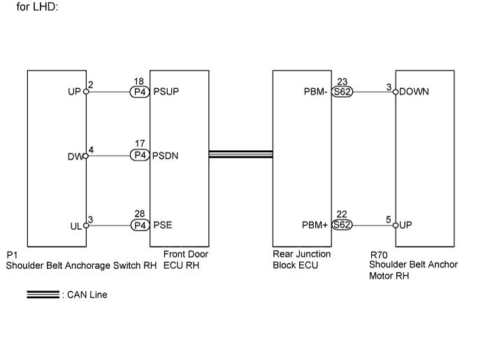
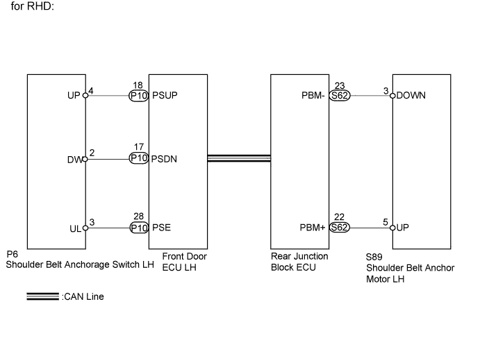
When the up or down switch of the shoulder belt anchorage switch is pressed, an UP or DOWN signal is sent to the front door ECU (passenger side). Then the signal is sent to the rear junction block ECU through CAN communication. Based on the received signal, the rear junction block ECU operates the shoulder belt anchor motor (passenger side) and moves the shoulder belt anchor (passenger side) up or down.
WIRING DIAGRAM
INSPECTION PROCEDURE
PROCEDURE
-
READ VALUE USING INTELLIGENT TESTER (SHOULDER BELT ANCHORAGE SWITCH)
-
Check the Data List for proper functioning of the shoulder belt anchorage switch.
Passenger Door (Front door ECU RH*1) (Front door ECU LH*2) : Tester Display Measurement Item / Range Normal Condition Diagnostic Note SEAT BELT ANCHOR UP Shoulder belt anchor up switch / OFF or ON ON: Up switch is pressed
OFF: Up switch is not pressed
- SEAT BELT ANCHOR DOWN Shoulder belt anchor down switch / OFF or ON ON: Down switch is pressed
OFF: Down switch is not pressed
- Tech Tips
*1: for LHD
*2: for RHD
OK Data List display changes correctly according to switch operation.
NG 
INSPECT HEIGHT ADJUSTABLE ANCHOR SWITCH (for Passenger Side) Click here
OK 
-
-
INSPECT SHOULDER BELT ANCHOR (for Passenger Side)
-
Remove the belt anchor (for passenger side) Click here.
-
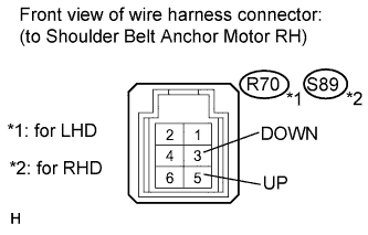
Apply battery voltage to the shoulder belt anchor motor.
-
Check the motor operation.
OK Measurement Condition Specified Condition Battery positive (+) → Terminal 3
Battery negative (-) → Terminal 5
Motor moves downward Battery positive (+) → Terminal 5
Battery negative (-) → Terminal 3
Motor moves upward
NG 
REPLACE SHOULDER BELT ANCHOR (for Passenger Side) Click here
OK
-
-
CHECK HARNESS AND CONNECTOR (SHOULDER BELT ANCHOR - REAR JUNCTION BLOCK ECU)
-
Disconnect the R70 or S89 anchor connector.
-
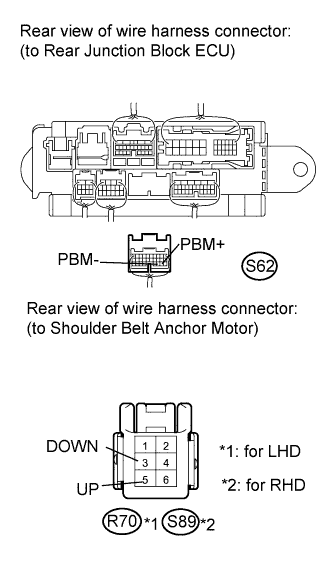
Disconnect the S62 ECU connector.
-
Measure the resistance according to the value(s) in the table below.
Standard Resistance for LHD: Tester Connection Condition Specified Condition R70-5 (UP) - S62-22 (PBM+) Always Below 1 Ω R70-3 (DOWN) - S62-23 (PBM-) R70-5 (UP) - Body ground Always 10 kΩ or higher R70-3 (DOWN) - Body ground for RHD: Tester Connection Condition Specified Condition S89-5 (UP) - S62-22 (PBM+) Always Below 1 Ω S89-3 (DOWN) - S62-23 (PBM-) S89-5 (UP) - Body ground Always 10 kΩ or higher S89-3 (DOWN) - Body ground
NG
REPAIR OR REPLACE HARNESS OR CONNECTOR
OK 
REPLACE LUGGAGE ROOM JUNCTION BLOCK (REAR JUNCTION BLOCK ECU)
-
-
INSPECT HEIGHT ADJUSTABLE ANCHOR SWITCH (for Passenger Side)
-
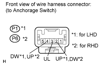
Remove the anchor switch (for passenger side) Click here
-
Measure the resistance according to the value(s) in the table below.
Standard Resistance for LHD: Tester Connection Switch Condition Specified Condition P1-2 (UP) - P1-3 (UL) Not operated 10 kΩ or higher P1-4 (DW) - P1-3 (UL) Not operated 10 kΩ or higher P1-2 (UP) - P1-3 (UL) Operated to UP side Below 1 Ω P1-4 (DW) - P1-3 (UL) Operated to UP side 10 kΩ or higher P1-2 (UP) - P1-3 (UL) Operated to DOWN side 10 kΩ or higher P1-4 (DW) - P1-3 (UL) Operated to DOWN side Below 1 Ω for RHD: Tester Connection Switch Condition Specified Condition P6-4 (UP) - P6-3 (UL) Not operated 10 kΩ or higher P6-2 (DW) - P6-3 (UL) Not operated 10 kΩ or higher P6-4 (UP) - P6-3 (UL) Operated to UP side Below 1 Ω P6-2 (DW) - P6-3 (UL) Operated to UP side 10 kΩ or higher P6-4 (UP) - P6-3 (UL) Operated to DOWN side 10 kΩ or higher P6-2 (DW) - P6-3 (UL) Operated to DOWN side Below 1 Ω
NG
REPLACE HEIGHT ADJUSTABLE ANCHOR SWITCH (for Passenger Side) Click here
OK
-
-
CHECK HARNESS AND CONNECTOR (HEIGHT ADJUSTABLE ANCHOR SWITCH - FRONT DOOR ECU)
-
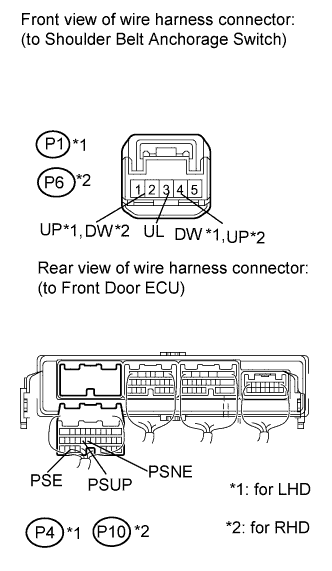
Disconnect the P1 or P6 switch connector.
-
Disconnect the P4 or P10 ECU connector.
-
Measure the resistance according to the value(s) in the table below.
Standard Resistance for LHD: Tester Connection Condition Specified Condition P1-2 (UP) - P4-18 (PSUP) Always Below 1 Ω P1-3 (UL) - P4-28 (PSE) P1-4 (DW) - P4-17 (PSDN) P1-2 (UP) - Body ground Always 10 kΩ or higher P1-3 (UL) - Body ground P1-4 (DW) - Body ground for RHD: Tester Connection Condition Specified Condition P6-4 (UP) - P10-18 (PSUP) Always Below 1 Ω P6-3 (UL) - P10-28 (PSE) P6-2 (DW) - P10-17 (PSDN) P6-4 (UP) - Body ground Always 10 kΩ or higher P6-3 (UL) - Body ground P6-2 (DW) - Body ground
NG
REPAIR OR REPLACE HARNESS OR CONNECTOR
OK
REPLACE FRONT DOOR ECU (for Passenger Side) Click here
-