AIRBAG SYSTEM, Diagnostic DTC:B1650/32

| DTC Code | DTC Name |
|---|---|
| B1650/32 | Occupant Detection Sensor Circuit Malfunction |
DESCRIPTION
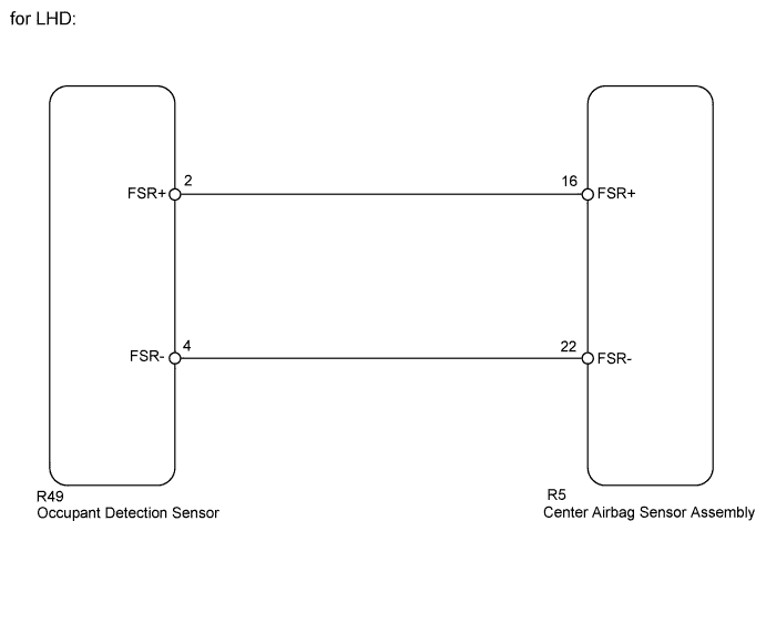
The occupant detection sensor circuit consists of the center airbag sensor assembly and the occupant detection sensor.
If the center airbag sensor assembly receives signals from the occupant detection sensor, it determines whether the front passenger airbag, the front passenger seat outer belt should be operated.
DTC B1650/32 is recorded when a malfunction is detected in the occupant detection sensor circuit.
| DTC Code | Detection Condition | Trouble Area |
|---|---|---|
| B1650/32 | One of the following conditions is met:
|
|
WIRING DIAGRAM

INSPECTION PROCEDURE
Note
-
After turning the power switch OFF, waiting time may be required before disconnecting the cable from the negative (-) auxiliary battery terminal. Therefore, make sure to read the disconnecting the cable from the negative (-) auxiliary battery terminal notices before proceeding with work Click here.
-
When disconnecting the cable from the negative (-) auxiliary battery terminal while performing repairs, some systems need to be initialized after the cable is reconnected Click here.
PROCEDURE
-
CHECK FOR DTC
-
Turn the power switch ON (IG), and wait for at least 60 seconds.
-
Clear the DTCs Click here.
-
Turn the power switch OFF.
-
Turn the power switch ON (IG), and wait for at least 60 seconds.
-
Check for DTCs Click here.
OK DTC B1650 is not output. Tech Tips
Codes other than DTC B1650 may be output at this time, but they are not related to this check.
NG 
CHECK CONNECTION OF CONNECTORS Click here
OK 
USE SIMULATION METHOD TO CHECK Click here
-
-
CHECK CONNECTION OF CONNECTORS
-
Turn the power switch OFF.
-
Disconnect the negative (-) terminal cable from the auxiliary battery, and wait for at least 90 seconds.
-
Check that the connectors are properly connected to the center airbag sensor assembly and the occupant detection sensor.
OK The connectors are properly connected.
NG 
CONNECT CONNECTORS PROPERLY
OK 
-
-
CHECK CONNECTORS
-
Disconnect the connectors from the center airbag sensor assembly and the occupant detection sensor.
-
Check that the connectors (on the center airbag sensor assembly side and the occupant detection sensor side) are not damaged.
OK The connectors are not deformed or damaged.
NG
REPLACE FLOOR WIRE
OK
-
-
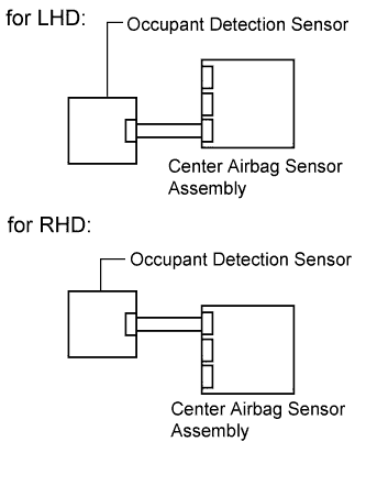
CHECK VEHICLE TYPE
-
Confirm the vehicle type.
Result Result Proceed to for LHD A for RHD B
B
CHECK OCCUPANT DETECTION SENSOR CIRCUIT Click here
A
-
-
CHECK OCCUPANT DETECTION SENSOR CIRCUIT
-
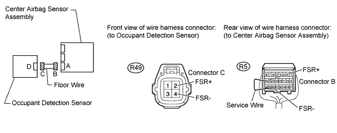
Using a service wire, connect terminals 16 (FSR+) and 22 (FSR-) of connector B.
Note
Do not forcibly insert the service wire into the terminals of the connector when connecting a service wire.
-
Measure the resistance according to the value(s) in the table below.
Standard resistance Tester Connection Condition Specified Condition R49-2 (FSR+) - R49-4 (FSR-) Always Below 1Ω -
Disconnect the service wire from connector B.
-
Measure the resistance according to the value(s) in the table below.
Standard resistance Tester Connection Condition Specified Condition R49-2 (FSR+) - R49-4 (FSR-) Always 1MΩ or higher R49-2 (FSR+) - Body ground Always 1MΩ or higher R49-4 (FSR-) - Body ground Always 1MΩ or higher -
Connect the negative (-) terminal cable to the auxiliary battery, and wait for at least 2 seconds.
-
Measure the voltage according to the value(s) in the table below.
Tester Connection Switch Condition Specified Condition R49-2 (FSR+) - Body ground Power switch ON (IG) Below 1 V R49-4 (FSR-) - Body ground Power switch ON (IG) Below 1 V
NG
REPLACE FLOOR WIRE
OK
-
-
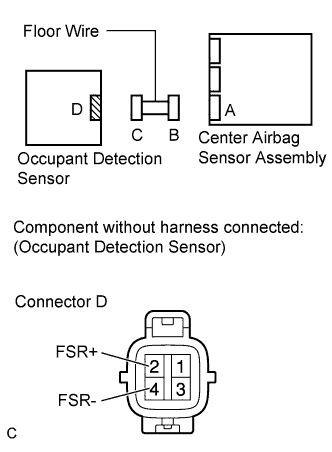
CHECK OCCUPANT DETECTION SENSOR
-
Measure the resistance according to the value(s) in the table below.
Note
Connect the positive tester lead to terminal FSR+, and the negative tester lead to terminal FSR-.
Standard resistance Tester Connection Condition Specified Condition Tester positive (+) → Terminal 2 (FSR+)
Tester negative (-) → Terminal 4 (FSR-)
Weight 15 kg (33 lb) applied 50k Ω or less Tester positive (+) → Terminal 2 (FSR+)
Tester negative (-) → Terminal 4 (FSR-)
No weight applied 50k Ω or higher
NG
REPLACE FRONT PASSENGER SIDE SEAT CUSHION PAD Click here
OK
REPLACE CENTER AIRBAG SENSOR ASSEMBLY Click here
-
-
CHECK OCCUPANT DETECTION SENSOR CIRCUIT
-
Turn the power switch OFF.
-
Disconnect the negative (-) terminal cable from the auxiliary battery, and wait for at least 90 seconds.
-
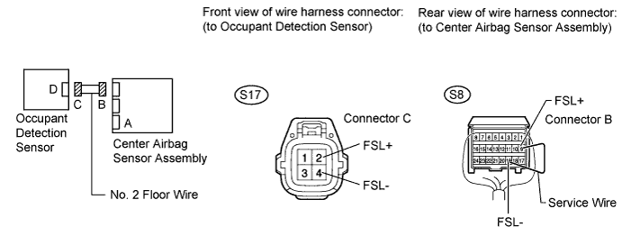
Disconnect the floor wire connector from the center airbag sensor assembly.
-
Using a service wire, connect terminal 9 (FSL+) and 19 (FSL-) of connector B.
Note
Do not forcibly insert the service wire into the terminals of the connector when connecting a service wire.
-
Measure the resistance according to the value(s) in the table below.
Standard resistance Tester Connection Condition Specified Condition S17-9 (FSL+) - S17-19 (FSL-) Always Below 1Ω -
Disconnect the service wire from connector B.
-
Measure the resistance according to the value(s) in the table below.
Standard resistance Tester Connection Condition Specified Condition S17-9 (FSL+) - S17-19 (FSL-) Always 1MΩ or higher S17-9 (FSL+) - Body ground Always 1MΩ or higher S17-19 (FSL-) - Body ground Always 1MΩ or higher -
Connect the negative (-) terminal cable to the auxiliary battery, and wait for at least 2 seconds.
-
Measure the voltage according to the value(s) in the table below.
Tester Connection Switch Condition Specified Condition S17-9 (FSL+) - Body ground Power switch ON (IG) Below 1 V S17-19 (FSL-) - Body ground Power switch ON (IG) Below 1 V
NG
REPLACE NO. 2 FLOOR WIRE
OK
-
-
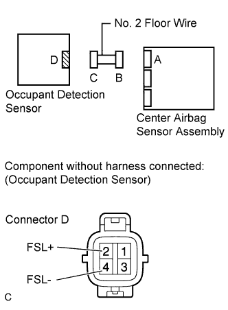
CHECK OCCUPANT DETECTION SENSOR
-
Measure the resistance according to the value(s) in the table below.
Note
Connect the positive tester lead to terminal FSL+, and the negative tester lead to terminal FSL-.
Standard resistance Tester Connection Condition Specified Condition Tester positive (+) → Terminal 2 (FSR+)
Tester negative (-) → Terminal 4 (FSR-)
Weight 15 kg (33 lb) applied 50k Ω or less Tester positive (+) → Terminal 2 (FSR+)
Tester negative (-) → Terminal 4 (FSR-)
No weight applied 50k Ω or higher
NG
REPLACE FRONT PASSENGER SIDE SEAT CUSHION PAD Click here
OK
REPLACE CENTER AIRBAG SENSOR ASSEMBLY Click here
-