DRIVER MONITOR ECU (for RHD) INSTALLATION

Tech Tips
A bolt without a torque specification is shown in the standard bolt chart Click here.
-
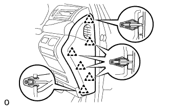
INSTALL DRIVER MONITOR ECU ASSEMBLY
-
Install the driver monitor ECU assembly with the 2 nuts.
- Torque:
- 8.5 N*m { 86 kgf*cm, 75 in.*lbf }
Note
-
Avoid any impact to the driver monitor ECU assembly.
-
Do not drop the driver monitor ECU assembly. If it is dropped, replace it with a new one.
-
Attach the guide and install the suspension control ECU with the 2 nuts.
- Torque:
- 6.0 N*m { 61 kgf*cm, 53 in.*lbf }
Note
-
Avoid any impact to the suspension control ECU.
-
Do not drop the suspension control ECU. If it is dropped, replace it with a new one.
-
Install the network gateway ECU with the 2 nuts.
- Torque:
- 7.5 N*m { 76 kgf*cm, 66 in.*lbf }
Note
-
Avoid any impact to the network gateway ECU.
-
Do not drop the network gateway ECU. If it is dropped, replace it with a new one.
-
Install the ECU unit with the 2 nuts.
-
Connect the 5 connectors.
-
-
INSTALL DRIVER SIDE KNEE AIRBAG ASSEMBLY
-
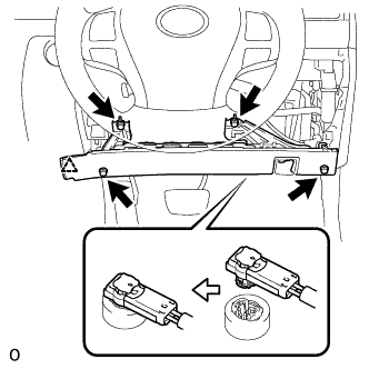
Connect the connector.
Note
When handling the airbag connector, take care not to damage the airbag wire harness.
-
Attach the clip to install the driver side knee airbag.
-
Install the 4 bolts.
- Torque:
- 10 N*m { 102 kgf*cm, 7 ft.*lbf }
-
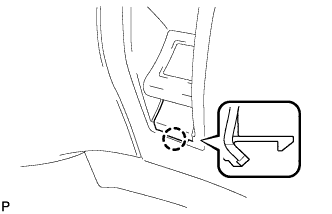
Attach the claw to install the lock lever.
-
Install the hood lock control lever sub-assembly.
-
-
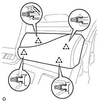
INSTALL NO. 1 INSTRUMENT PANEL SAFETY PAD SUB-ASSEMBLY
-
Connect each connector.
-
Attach the 5 clips and claw to install the No. 1 instrument panel safety pad sub-assembly.
-
Install the screw and bolt.
-
Attach the claw to install the switch base hole cover to the No. 1 instrument panel safety pad sub-assembly.
-
-
INSTALL NO. 1 INSTRUMENT PANEL UNDER COVER SUB-ASSEMBLY
-
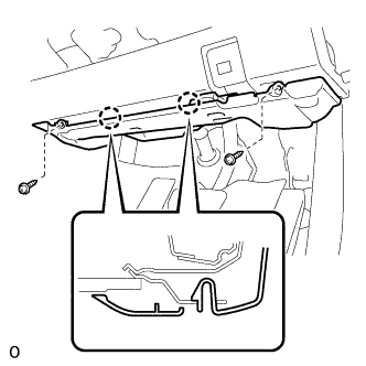
Connect each connector and each clamp.
-
Attach the 2 claws to connect the DLC3.
-
Attach the 2 claws to install the No. 1 instrument panel under cover sub-assembly.
-
Install the 2 screws.
-
-
INSTALL INSTRUMENT PANEL ORNAMENT
-
Connect the connector.
-
Attach the 4 clips to install the instrument panel ornament.
-
-
INSTALL INSTRUMENT SIDE PANEL RH
-
Attach the 6 clips to install the instrument side panel RH.
-
-
CONNECT CABLE TO AUXILIARY BATTERY NEGATIVE TERMINAL
Note
When disconnecting the cable, some systems need to be initialized after the cable is reconnected Click here.
-
INSTALL BATTERY SERVICE HOLE COVER LH
-

Text in Illustration *A for Standard *B for Ottoman Attach the battery service hole cover LH with the clip and fastening tape.
-
-
INSTALL DECK TRIM SIDE BOARD LH (w/o Spare Tire)
-

Attach the 2 clips to install the deck trim side board LH.
-
-
INSTALL DECK BOARD ASSEMBLY (w/o Spare Tire)

-
INSTALL LUGGAGE COMPARTMENT MAT SUB-ASSEMBLY (w/ Spare Tire)

-
CHECK SRS WARNING LIGHT