DRIVER MONITOR CAMERA INSTALLATION

Tech Tips
-
Use the same procedures for LHD and RHD vehicles.
-
The procedures listed below are for LHD vehicles.
-
INSTALL DRIVER MONITOR CAMERA
-
Attach the 2 claws and install the driver monitor camera with the 2 screws.
- Torque:
- 1.8 N*m { 18 kgf*cm, 16 in.*lbf }
-
-
INSTALL DRIVER MONITOR BRACKET
-
Attach the guide and install the driver monitor bracket with the screw.
- Torque:
- 1.8 N*m { 18 kgf*cm, 16 in.*lbf }
-
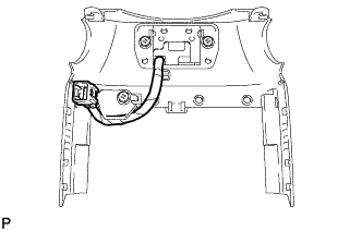
Attach the claw to connect the driver monitor camera connector.
Note
Make sure that the wire harness of the driver monitor camera is positioned as shown in the illustration.
-
-
INSTALL STEERING COLUMN COVER
-
for Upper Side:
-
Attach the claw to install the steering column cover.
-
Connect the driver monitor camera connector.
-
Attach the 4 clips to install the instrument cluster finish panel sub-assembly.
-
-
for Lower Side:
-
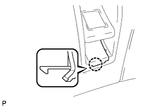
Attach the 2 claws to install the steering column cover.
-
Install the 3 screws.
-
-
-
INSTALL NO. 1 INSTRUMENT PANEL SAFETY PAD SUB-ASSEMBLY
-
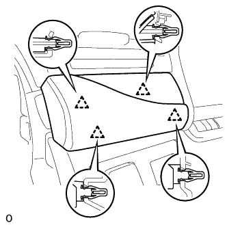
Connect each connector.
-
Attach the 5 clips and claw to install the No. 1 instrument panel safety pad sub-assembly.
-
Install the screw <C> and bolt.
-
Attach the claw to install the switch base hole cover to the No. 1 instrument panel safety pad sub-assembly.
-
-
INSTALL INSTRUMENT PANEL ORNAMENT
-
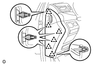
Connect the connector.
-
Attach the 4 clips to install the instrument panel ornament.
-
-
INSTALL INSTRUMENT SIDE PANEL LH
-
Attach the 6 clips to install the instrument side panel LH.
-
-
ENABLE AUTO TILT AWAY FUNCTION
Note
Restore the Autoaway/Return function setting to the previous condition by changing the customize parameter Click here.