AIR CONDITIONING AMPLIFIER INSTALLATION

Tech Tips
-
Use the same procedure for RHD and LHD vehicles.
-
The procedure listed below is for LHD vehicles.
-
A bolt without a torque specification is shown in the standard bolt chart Click here.
-
INSTALL AIR CONDITIONING AMPLIFIER ASSEMBLY
-
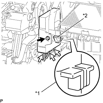
Text in Illustration *1 Protrusion Part *2 Fitting Point Insert the protrusion part of the air conditioning amplifier assembly to the fitting point of the air conditioning unit, and then align the hole of the air conditioning unit assembly with the locating pin of the air conditioning unit and install the screw.
-
Connect the 3 connectors.
-
-
INSTALL NO. 2 AIR DUCT SUB-ASSEMBLY
-
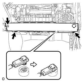
Attach the 2 claws to install the No. 2 air duct sub-assembly.
-
Install the screw.
-
-
INSTALL GLOVE COMPARTMENT DOOR ASSEMBLY
-
Connect each connector and attach each wire harness clamp.
-
Install the glove compartment door assembly with the 5 screws <C>.
-
-
INSTALL FRONT PASSENGER SIDE KNEE AIRBAG ASSEMBLY
-
Check that the power switch is off.
-
Check that the cable is disconnected from the negative (-) auxiliary battery terminal.
CAUTION:
Wait at least 90 seconds after disconnecting the cable from the negative (-) auxiliary battery terminal to disable the SRS system.
-
Push in the lock to connect the airbag connector.
-
Connect the airbag connector to the front passenger side knee airbag assembly
Note
When connecting airbag connector, take care not to damage the airbag wire harness.
-
Attach the claw to install the front passenger side knee airbag assembly.
-
Install the 3 bolts.
- Torque:
- 10 N*m { 102 kgf*cm, 7 ft.*lbf }
Note
Confirm that the front passenger side knee airbag assembly is installed securely without any excessive gaps and is not protruding outward.
-
-
INSTALL LOWER INSTRUMENT PANEL
-
Attach the 2 claws and clip to install the lower instrument panel.
-
-
INSTALL NO. 2 INSTRUMENT PANEL UNDER COVER SUB-ASSEMBLY
-
Connect the connector.
-
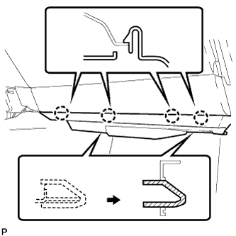
Insert the 2 guides.
-
Attach the 4 claws to install the No. 2 instrument panel under cover sub-assembly.
-
-
INSTALL INSTRUMENT SIDE PANEL RH
-
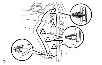
Attach the 6 clips to install the instrument side panel RH.
-
-
CONNECT CABLE TO AUXILIARY BATTERY NEGATIVE TERMINAL
Note
When disconnecting the cable, some systems need to be initialized after the cable is reconnected Click here.
-
INSTALL BATTERY SERVICE HOLE COVER LH
-

Text in Illustration *A for Standard *B for Ottoman Attach the battery service hole cover LH with the clip and fastening tape.
-
-
INSTALL DECK TRIM SIDE BOARD LH (w/o Spare Tire)
-
INSTALL DECK BOARD ASSEMBLY (w/o Spare Tire)

-
INSTALL LUGGAGE COMPARTMENT MAT SUB-ASSEMBLY (w/ Spare Tire)

-
CHECK SRS WARNING LIGHT