PRE-CRASH SAFETY SYSTEM TERMINALS OF ECU

-
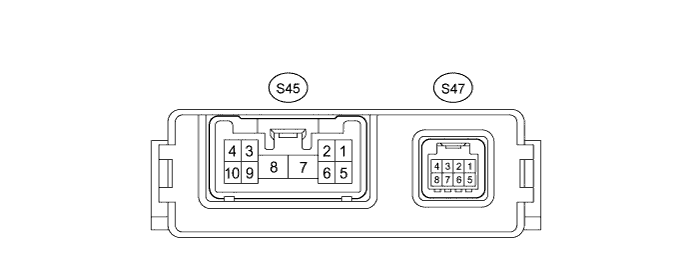
CHECK SEAT BELT CONTROL ECU
-
Disconnect the S45 and S47 ECU connectors.
-
Measure the resistance and voltage according to the value(s) in the table below.
Terminal No. (Symbols) Wiring Color Terminal Description Condition Specified Condition S45-7 (+B) - Body ground B - Body ground Battery Always 11 to 14 V S45-8 (PGND) - Body ground W-B - Body ground Body ground Always Below 1 Ω S47-8 (IG1) - Body ground G - Body ground Seat belt control ECU power supply Power switch on (IG) 11 to 14 V S47-8 (IG1) - Body ground G - Body ground Seat belt control ECU power supply Power switch off Below 1 V If the result is not as specified, there may be a malfunction on the wire harness side.
-
Reconnect the S45 and S47 connectors.
-
Measure the voltage according to the value(s) in the table below.
Terminal No. (Symbols) Wiring Color Terminal Description Condition Specified Condition S45-2 (MOR+) - S45-1 (MOR-) R - G Seat belt motor RH power supply Power switch on (IG) 4.0 to 8.5 V S45-2 (MOR+) - S45-1 (MOR-) R - G Seat belt motor RH power supply Power switch off Below 1 V S45-3 (MOL+) - S45-4 (MOL-) W - L Seat belt motor LH power supply Power switch on (IG) 4.0 to 8.5 V S45-3 (MOL+) - S45-4 (MOL-) W - L Seat belt motor LH power supply Power switch off Below 1 V If the result is not as specified, the ECU may be malfunctioning.
-
-
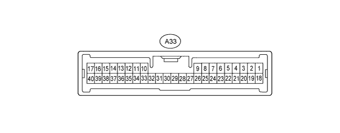
CHECK DRIVING SUPPORT ECU
-
Disconnect the A33 ECU connector.
-
Measure the voltage and resistance according to the value(s) in the table below.
Terminal No. (Symbols) Wiring Color Terminal Description Condition Specified Condition A33-13 (B) - Body ground Y - Body ground Power supply Power switch on (IG) 11 to 14 V A33-13 (B) - Body ground Y - Body ground Power supply Power switch off Below 1 V A33-25 (GND) - Body ground W-B - Body ground Body ground Always Below 1 Ω A33-11 (STP-) - Body ground BE - Body ground Stop light switch signal input Brake pedal is depressed 11 to 14 V A33-11 (STP-) - Body ground BE - Body ground Stop light switch signal input Brake pedal is released Below 1 V A33-34 (ST1-) - Body ground G - Body ground Stop light switch signal input Power switch on (IG),
brake pedal is released
11 to 14 V A33-34 (ST1-) - Body ground G - Body ground Stop light switch signal input Power switch on (IG),
brake pedal is depressed
Below 1 V A33-6 (FCAS) - Body ground L - Body ground Pre-crash brake cancel switch signal Pre-crash brake cancel switch ON Below 1 Ω A33-6 (FCAS) - Body ground L - Body ground Pre-crash brake cancel switch signal Pre-crash brake cancel switch OFF 10 kΩ or higher If the result is not as specified, there may be a malfunction on the wire harness side.
-
-
CHECK ACTIVE HEADREST CONTROL ECU LH

-
Disconnect the e73 ECU connector.
-
Measure the resistance and voltage according to the value(s) in the table below.
Terminal No. (Symbols) Wiring Color Terminal Description Condition Specified Condition e73-3 (IG1) - Body ground V - Body ground Active headrest control ECU LH power supply Power switch on (IG) 11 to 14 V e73-3 (IG1) - Body ground V - Body ground Active headrest control ECU LH power supply Power switch off Below 1 V e73-1 (GND) - Body ground W-B - Body ground Body ground Always Below 1 Ω e73-4 (LSW) - Body ground* W-B - Body ground Terminal for identification of front LH Always Below 1 Ω Tech Tips
*: Terminal LSW is used for distinguishing between the active headrest control ECU LH and RH. Terminal LSW of the active headrest control ECU LH is connected.
If the result is not as specified, there may be a malfunction on the wire harness side.
-
-
CHECK ACTIVE HEADREST CONTROL ECU RH

-
Disconnect the e60 ECU connector.
-
Measure the resistance and voltage according to the value(s) in the table below.
Terminal No. (Symbols) Wiring Color Terminal Description Condition Specified Condition e60-3 (IG1) - Body ground L - Body ground Active headrest control ECU RH power supply Power switch on (IG) 11 to 14 V e60-3 (IG1) - Body ground L - Body ground Active headrest control ECU RH power supply Power switch off Below 1 V e60-1 (GND) - Body ground W-B - Body ground Body ground Always Below 1 Ω If the result is not as specified, there may be a malfunction on the wire harness side.
-
-
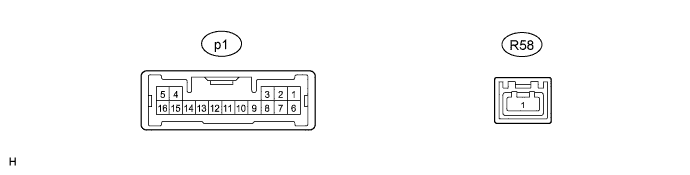
CHECK OBJECT RECOGNITION ECU
-
Disconnect the p1 ECU connector.
-
Measure the resistance and voltage according to the value(s) in the table below.
Terminal No. (Symbols) Wiring Color Terminal Description Condition Specified Condition p1-6 (IG) - Body ground V - Body ground Object recognition ECU power supply Power switch on (IG) 11 to 14 V p1-6 (IG) - Body ground V - Body ground Object recognition ECU power supply Power switch off Below 1 V p1-10 (GND) - Body ground W-B - Body ground Body ground Always Below 1 Ω If the result is not as specified, there may be a malfunction on the wire harness side.
-