REAR EVAPORATOR TEMPERATURE SENSOR (w/ Rear Air Conditioning System) INSTALLATION

-
INSTALL NO. 2 COOLER THERMISTOR

Text in Illustration *a 1 Fin Note
If reusing the evaporator, do not insert the sensor into a location where the No. 2 cooler thermistor was previously inserted. Insert the No. 2 cooler thermistor to a location that is 1 fin to the right or left of its previous location.
-
Install the No. 2 cooler thermistor as shown in the illustration.
Area Standard Dimension a 85 to 95 mm (3.35 to 3.74 in.) b 45 to 55 mm (1.78 to 2.16 in.) c 34.3 mm (1.35 in.) d 114.8 mm (4.52 in.) e 128.1 mm (5.04 in.)
-
-
INSTALL REAR EVAPORATOR SUB-ASSEMBLY
-

Sufficiently apply compressor oil to 2 new O-rings and the fitting surface of the hose joint.
Compressor oil ND-OIL 11 or equivalent -
Install the 2 O-rings to the rear evaporator sub-assembly.
-
Install the rear evaporator sub-assembly.
-
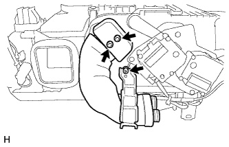
Install the rear cooling unit case (upper) and attach the clamp as shown in the illustration.

-
Install the 6 clips and 8 screws.
Text in Illustration *1 Air Conditioner Thermistor Assembly *a Rear Cooling Unit Case (Upper) -

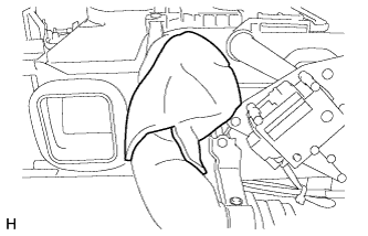
Install new packing as shown in the illustration.
-
-
INSTALL NO. 2 WIRING AIR CONDITIONER HARNESS SUB-ASSEMBLY
-
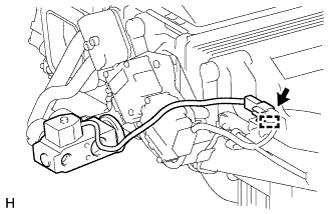
Install the No. 2 wiring air conditioner harness sub-assembly.

-
Connect the connectors and attach the clamps.
-
Install a new cable tie.
-
-
INSTALL REAR BLOWER WITH FAN MOTOR SUB-ASSEMBLY

-
Install the rear blower with fan motor sub-assembly with the 3 screws.
-
Connect the connector.
-

Install the air duct RH with the 3 screws.
-

Install the air duct LH with the 3 screws.
-
-
INSTALL NO. 3 REAR COOLING UNIT DAMPER SERVO SUB-ASSEMBLY
-

Install the No. 3 rear cooling unit damper servo sub-assembly with the 3 screws.
-
Connect the 2 connectors.
-
-
INSTALL AIR CONDITIONING TUBE ASSEMBLY
-
Sufficiently apply compressor oil to 2 new O-rings and the fitting surface of the hose joint.
Compressor oil ND-OIL 11 or equivalent -
Install the 2 O-rings to the air conditioning tube assembly.
-
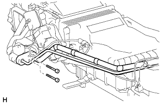
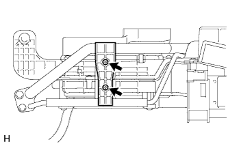
Install the air conditioning tube assembly to the rear evaporator sub-assembly.
-
Using a 4 mm hexagon wrench, install the 2 hexagon bolts.
- Torque:
- 3.5 N*m { 35 kgf*cm, 30 in.*lbf }
-
Install the screw.
-
Install new packing.
-
-
INSTALL REAR COOLING UNIT EXPANSION VALVE
-
Install the rear cooling unit expansion valve.
-
Connect the connector and attach the clamp.
-
-
INSTALL NO. 2 AIR CONDITIONING TUBE AND ACCESSORY ASSEMBLY
-
Sufficiently apply compressor oil to 2 new O-rings and the fitting surface of the hose joint.
Compressor oil ND-OIL 11 or equivalent -
Install the 2 O-rings to the No. 2 air conditioning tube and accessory assembly.
-
Install the No. 2 air conditioning tube and accessory assembly to the rear evaporator sub-assembly.
-
Using a 4 mm hexagon wrench, install the 2 hexagon bolts.
- Torque:
- 3.5 N*m { 35 kgf*cm, 30 in.*lbf }
-

Text in Illustration *1 Packing *2 Butyl Tape Install new packing and butyl tape as shown in the illustration.
Note
Apply butyl tape so that none of the No. 1 expansion valve is exposed.
-
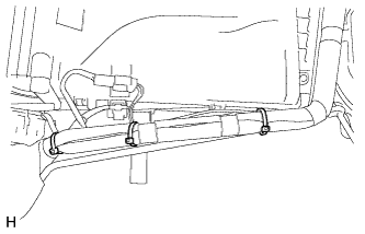
Install 3 new cable ties.
-
Install the piping parts clamp with the 2 screws.
-
-
INSTALL NO. 2 REAR COOLING UNIT DAMPER SERVO SUB-ASSEMBLY
-

Install the No. 2 rear cooling unit damper servo sub-assembly with the 3 screws.
-
Connect the connector.
-
-
INSTALL NO. 1 REAR COOLING UNIT DAMPER SERVO SUB-ASSEMBLY (for LH Side)
-

Text in Illustration *a Alignment Point Align the No. 1 rear cooling unit damper servo sub-assembly as shown in the illustration and install it with the 2 screws.
-
Connect the connector.
-
-
INSTALL NO. 1 REAR COOLING UNIT DAMPER SERVO SUB-ASSEMBLY (for RH Side)
-

Text in Illustration *a Alignment Point Align the No. 1 rear cooling unit damper servo sub-assembly as shown in the illustration and install it with the 2 screws.
-
Connect the connector.
-
-
INSTALL SMOKE SENSOR
-

Install the smoke sensor with the 2 screws.
-
Connect the connector.
-
-
INSTALL REAR COOLER FILTER
-

Install the rear cooler filter as shown in the illustration.
-
-
INSTALL DRAIN COOLER HOSE
-

Text in Illustration *a Protruding Part Install the drain cooler hose as shown in the illustration.
-
-
INSTALL REAR COOLING UNIT ASSEMBLY