FRONT EVAPORATOR TEMPERATURE SENSOR INSTALLATION

Tech Tips
A bolt without a torque specification is shown in the standard bolt chart Click here.
-
INSTALL NO. 1 COOLER THERMISTOR
Note
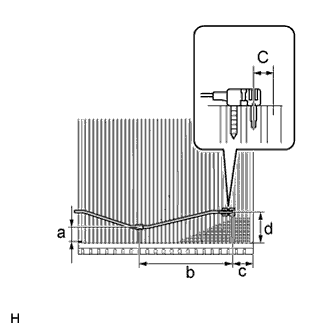
If reusing the evaporator, do not insert the sensor into a location where the sensor was previously inserted. Insert the sensor within range C shown in the illustration.
-
Install the No. 1 cooler thermistor as shown in the illustration.
Area Standard Dimension a 20 to 30 mm (0.788 to 1.18 in.) b 154.1 mm (6.07 in.) c 33.3 mm (1.31 in.) d 45 to 55 mm (1.78 to 2.16in.) -
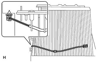
Attach the clamp.
-
-
INSTALL NO. 1 COOLER EVAPORATOR SUB-ASSEMBLY
-
Install the No. 1 evaporator sub-assembly to the front cooling unit case (front side).
-
Attach the 3 claws to install the front cooling unit case (back side) to the front cooling unit case (front case).
-
Install the 6 screws.
-
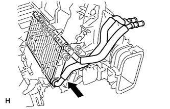
Attach the hook to install the bracket to the air conditioner tube assembly, and install the holding spring.
-
Install a new packing to the bracket.
-
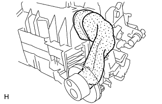
Tightly wrap a new No. 2 cooling unit packing to prevent exposure of the expansion valve and air conditioner tube assembly, and then wrap a new No. 3 cooling unit packing over the No. 2 cooling unit packing.
-
-
INSTALL HEATER RADIATOR UNIT SUB-ASSEMBLY
-
Install the heater radiator unit sub-assembly as shown in the illustration.
-
Install the clamp with the screw.
-
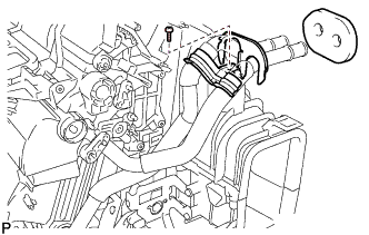
Install a new packing to the clamp.
-
-
INSTALL AIR CONDITIONER HARNESS
-
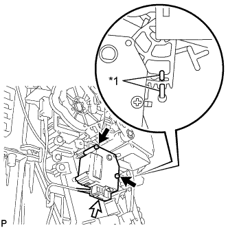
INSTALL QUICK HEATER ASSEMBLY
-
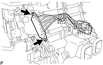
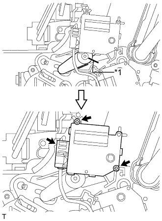
Install the quick heater assembly with the 2 screws.
-
Attach the 2 connector clamps and harness clamp.
-
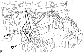
Install the bracket with the 3 screws.
-
-
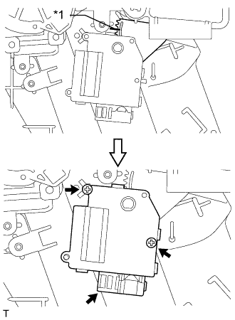
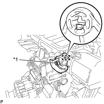
INSTALL AIR OUTLET SERVO MOTOR LH (Foot/Def)
-
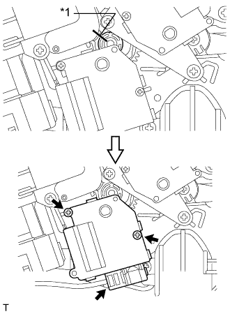
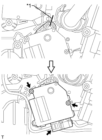
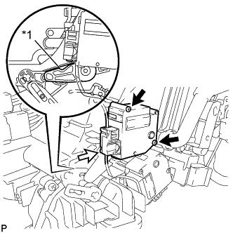
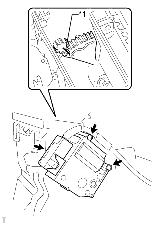
Install the front air outlet servo motor LH (foot/def) with the 3 screws.
-
Connect the connector.
-
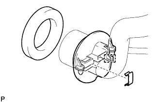
Text in Illustration *1 Pin Attach the claw to install the main plate as shown in the illustration.
-
-
INSTALL AIR OUTLET SERVO MOTOR RH (Foot/Def)
-
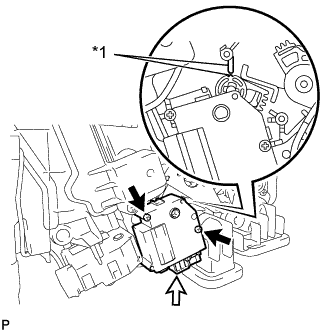
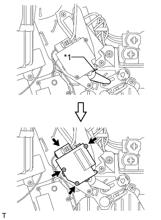
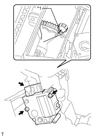
Install the air outlet servo motor RH (foot/def) with the 3 screws.
-
Connect the connector.
-
Text in Illustration *1 Pin Attach the claw to install the main plate.
-
-
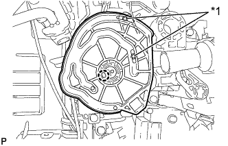
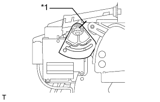
INSTALL MAX HOT BYPASS SERVO MOTOR (Hot)
Text in Illustration *1 Alignment Marks
-
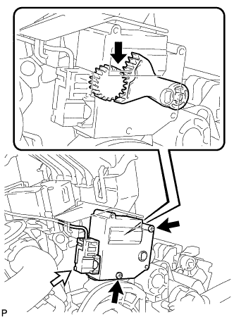
When reusing the max hot air bypass servo motor (hot):
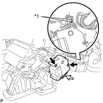
Align the moving parts and air conditioning unit as shown in the illustration and install the max hot air bypass servo motor (hot) with the 2 screws.
-
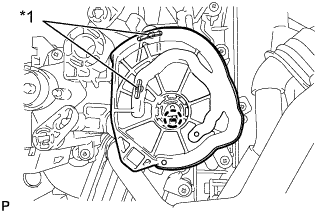
Text in Illustration *1 Protruding Part When using the new max hot air bypass servo motor (hot):
Align the protruding parts on the case and cover, and then install the max hot air bypass servo motor (hot) with the 2 screws.
-
Connect the connector.
-
-
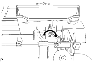
INSTALL AIR MIX SERVO MOTOR LH (Hot)
-
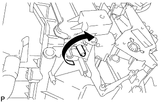
Make sure that the rod does not rotate further by trying to rotate it clockwise.
-
Install the air mix servo motor LH (Hot) with the 2 screws.
-
Connect the connector.
-
-
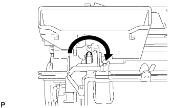
INSTALL AIR MIX SERVO MOTOR RH (Hot)
-
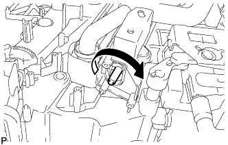
Make sure that the rod does not rotate further by trying to rotate it clockwise.
-
Install the air mix servo motor RH (Hot) with the 2 screws.
-
Connect the connector.
-
-
INSTALL AIR MIX SERVO MOTOR LH (Front A/C Rear Air Flow)
Text in Illustration *1 Alignment Marks
-
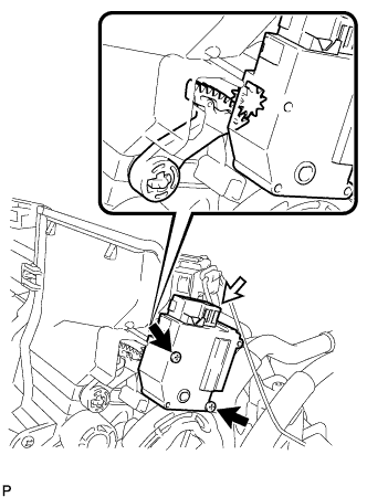
When reusing the air mix servo motor LH (front A/C rear air flow):
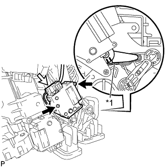
Align the moving parts and air conditioning unit as shown in the illustration and install the air mix servo motor LH (front A/C rear air flow) with the 2 screws.
-
Text in Illustration *1 Protruding Part When using the new air mix servo motor LH (front A/C rear air flow):
Align the protruding parts on the case and cover, and then install the air mix servo motor LH (front A/C rear air flow) with the 2 screws.
-
Connect the connector.
-
-
INSTALL AIR MIX SERVO MOTOR RH (Front A/C Rear Air Flow)
Text in Illustration *1 Alignment Marks
-
When reusing the air mix servo motor RH (front A/C rear air flow):
Align the moving parts and air conditioning unit as shown in the illustration and install the air mix servo motor RH (front A/C rear air flow) with the 2 screws.
-
Text in Illustration *1 Protruding Part When using the new air mix servo motor RH (front A/C rear air flow):
Align the protruding parts on the case and cover, and then install the air mix servo motor RH (front A/C rear air flow) with the 2 screws.
-
Connect the connector.
-
-
INSTALL AIR OUTLET SERVO MOTOR LH (Front A/C Rear Air Flow)
Text in Illustration *1 Alignment Marks
-
When reusing the air outlet servo motor LH (front A/C rear air flow):
Align the moving parts and air conditioning unit as shown in the illustration and install the air outlet servo motor LH (front A/C rear air flow) with the 2 screws.
-
Text in Illustration *1 Matchmark When using the new air outlet servo motor LH (front A/C rear air flow):
Align the lever with the matchmark as shown in the illustration.
-
Install the air outlet servo motor LH (front A/C rear air flow) with the 2 screws.
-
Connect the connector.
-
-
INSTALL AIR OUTLET SERVO MOTOR RH (Front A/C Rear Air Flow)
Text in Illustration *1 Alignment Marks
-
When reusing the air outlet servo motor RH (front A/C rear air flow):
Align the moving parts and air conditioning unit as shown in the illustration and install the air outlet servo motor RH (front A/C rear air flow) with the 2 screws.
-
Text in Illustration *1 Stopper Set the lever to the stopper as shown in the illustration.
-
Install the air outlet servo motor RH (front A/C rear air flow) with the 2 screws.
-
Connect the connector.
-
-
INSTALL AIR OUTLET SERVO MOTOR LH (Face)
-
Install the air outlet servo motor LH (face) with the 2 screws.
-
Connect the connector.
-
Text in Illustration *1 Alignment Marks When reusing the air outlet servo motor LH (face):
Align the moving parts and air conditioning unit as shown in the illustration and install the lever.
-
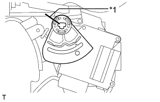
Text in Illustration *1 Cutout Part When using the new air outlet servo motor LH (face):
Set the lever so that the cutout part engages with a tooth of the gear, and then attach the 3 claws to install the lever.
-
-
INSTALL AIR OUTLET SERVO MOTOR RH (Face)
-
Install the air outlet servo motor RH (face) with the 2 screws.
-
Connect the connector.
-
Text in Illustration *1 Alignment Marks When reusing the air outlet servo motor RH (face):
Align the moving parts and air conditioning unit as shown in the illustration and install the lever.
-
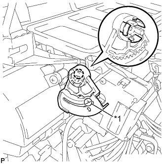
Text in Illustration *1 Cutout Part When using the new air outlet servo motor RH (face):
Set the lever so that the cutout part engages with a tooth of the gear, and then attach the claw to install the lever.
-
-
INSTALL AIR MIX SERVO MOTOR LH (Cool)
-
Make sure that the rod does not rotate further by trying to rotate it clockwise.
-
Install the air mix servo motor LH (cool) with the 2 screws.
-
Connect the connector.
-
-
INSTALL AIR MIX SERVO MOTOR RH (Cool)
-
Make sure that the rod does not rotate further by trying to rotate it clockwise.
-
Install the air mix servo motor RH (cool) with the 2 screws.
-
Connect the connector.
-
-
INSTALL COOL AIR BYPASS SERVO MOTOR LH
-
When reusing the cool air bypass servo motor LH:
Align the moving parts and air conditioning unit as shown in the illustration and install the damper servo with the 2 screws.
Text in Illustration *1 Alignment Marks -
When using the new cool air bypass servo motor LH:
Set the lever so that the cutout part engages with a tooth of the gear, and then install the cool air bypass servo motor LH with the 2 screws.
-
Connect the connector.
-
-
INSTALL COOL AIR BYPASS SERVO MOTOR RH
-
When reusing the cool air bypass servo motor RH:
Align the moving parts and air conditioning unit as shown in the illustration and install the damper servo with the 2 screws.
Text in Illustration *1 Alignment Marks -
When using the new cool air bypass servo motor RH:
Set the lever so that the cutout part engages with a tooth of the gear, and then install the cool air bypass servo motor RH with the 2 screws.
-
Connect the connector.
-
-
INSTALL NO. 1 AIR DUCT SUB-ASSEMBLY
-
Attach the 4 claws to install the No. 1 duct sub-assembly.
-
-
INSTALL NO. 2 AIR DUCT SUB-ASSEMBLY
-
Attach the 4 claws to install the No. 2 duct sub-assembly.
-
-
INSTALL BLOWER ASSEMBLY
-
Attach the claw to install the blower assembly.
-
Connect the connector.
-
Install the screw.
-
-
INSTALL FRONT AIR CONDITIONING UNIT