COMPRESSOR INSTALLATION

-
ADJUST COMPRESSOR OIL
-
When replacing the compressor and magnetic clutch with a new one, gradually discharge the refrigerant gas from the service valve, and drain the following amount of oil from the new compressor and magnetic clutch before installation.
Standard (Oil capacity inside the new compressor and magnetic clutch: 130 + 15 cc (4.6 + 0.51 fl. oz.)) - (Remaining oil amount in the removed compressor and magnetic clutch) = (Oil amount to be removed from the new compressor when replacing) Note
-
When checking the compressor oil level, observe the A/C system's precautions.
-
If a new compressor and magnetic clutch is installed without removing some oil remaining in the pipes of the vehicle, the oil amount will be too large. This prevents heat exchange in the refrigerant cycle and causes refrigerant failure.
-
If the volume of oil remaining in the removed compressor and magnetic clutch is too small, check for oil leakage.
-
Be sure to use ND-OIL 11 or equivalent for compressor oil.
-
-
-
INSTALL HEATER WIRE
-
INSTALL WITH MOTOR COMPRESSOR ASSEMBLY
-
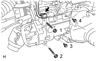
Using an E8 ''TORX'' socket wrench, install the with motor compressor assembly with the 2 stud bolts
- Torque:
- 10 N*m { 102 kgf*cm, 7 ft.*lbf }
-
Install the 2 bolts and 2 nuts.
- Torque:
- 25 N*m { 250 kgf*cm, 18 ft.*lbf }
Note
Tighten the nuts and bolts in the order shown in the illustration to install the cooler compressor.
-
Connect the connector.
-
-
INSTALL ENGINE AND TRANSMISSION
-
ADD COMPRESSOR OIL
-
When performing work on air conditioning parts, follow the oil guidelines below in order to protect the cooler compressor.
Part and Condition Oil Level (cc) Work Procedure Compressor replacement -100 to -120 Drain oil from new compressor Condenser replacement 35 to 55 Fill oil into replacement part Evaporator replacement 40 to 60 A/C pipe replacement High pressure 5 to 25 Low pressure When discharging refrigerant gas quickly 30 to 50 While applying vacuum, use manifold gauge to fill oil from low pressure side valve
-
-
CHARGE REFRIGERANT
-
Perform vacuum purging using a vacuum pump or appropriate equipment.
-
Charge the air conditioning system with refrigerant.
Refrigerant type HFC-134a (R134a) 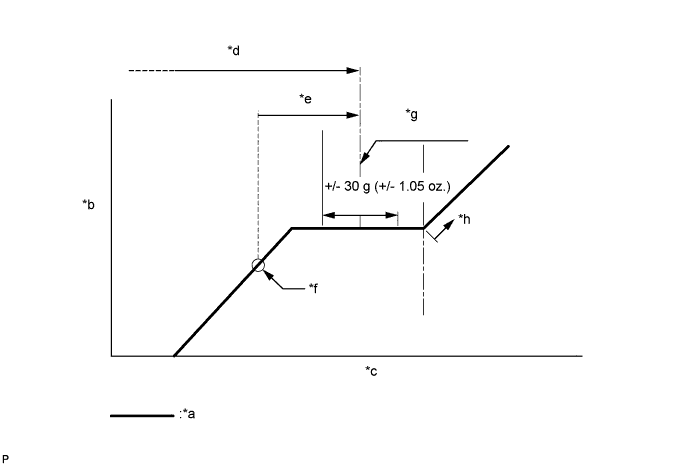
Text in Illustration *a Sub-cool System *b High Pressure *c Refrigerant Amount *d Standard charge amount *e Charge additional 100 g (3.5 oz.) *f Point where bubbles disappear *g Mean value in proper range *h Overcharged Standard charge amount 810 to 870 g (28.6 to 30.7 oz.) - SST
- 09985-20010 ( 09985-02010, 09985-02050, 09985-02060, 09985-02070, 09985-02080, 09985-02090, 09985-02110, 09985-02130, 09985-02140, 09985-02150 )
Note
-
Do not turn the A/C switch on before charging the air conditioning system with refrigerant. Doing so may cause the compressor to work without refrigerant, resulting in overheating of the compressor.
-
The refrigerant amount should be checked by quantity (weight).
Tech Tips
Make sure that sufficient refrigerant is available to recharge the system when using a refrigerant recovery unit. Refrigerant recovery units are not always able to recover 100% of the refrigerant from an air conditioning system.
-
-
WARM UP ENGINE
-
Keep the A/C switch on for at least 2 minutes to warm up the compressor.
Note
To prevent damage to the compressor, be sure to warm up the compressor when turning the air conditioning on after removing and installing air conditioning system lines (including the compressor).
-
-
CHECK FOR REFRIGERANT GAS LEAK
-
After recharging the air conditioning system with refrigerant, check for refrigerant leaks using a halogen leak detector.
-
Carry out the test under the following conditions:
-
Power switch off.
-
Secure good ventilation (the halogen leak detector may react to volatile gases which are not refrigerant, such as gasoline vapor and exhaust gas).
-
Repeat the inspection 2 or 3 times.
-
Measure the pressure to make sure that there is some refrigerant remaining in the air conditioning system (pressure when the compressor is off: approx. 392 to 588 kPa (3.9 to 5.9 kgf/cm2, 57 to 85 psi)).
-
-
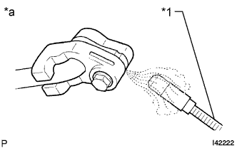
Text in Illustration *1 Halogen Leak Detector *a Check for Leak Using a halogen leak detector, check for refrigerant leaks from the air conditioning system.
-
If a refrigerant leak is not detected from the drain hose, remove the blower motor control from the cooling unit. Insert the halogen leak detector sensor into the unit and check for a leak.
-
Disconnect the pressure sensor connector and leave it for approximately 20 minutes. Bring the halogen leak detector close to the pressure sensor and check for a leak.
Tech Tips
When checking for leaks, the presence of oily dirt at a joint can indicate a leak.
-