REAR COOLING UNIT (w/ Rear Air Conditioning System) INSTALLATION

-
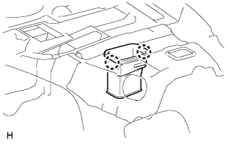
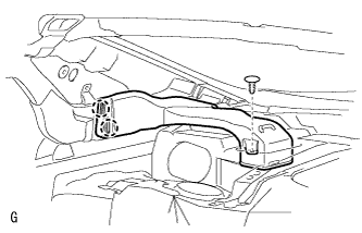
INSTALL REAR COOLING UNIT ASSEMBLY
-
Install the rear cooling unit assembly and connect the drain cooler hose as shown in the illustration.
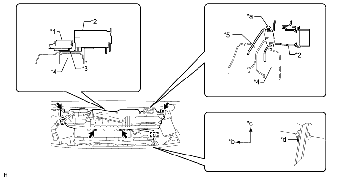
Text in Illustration *1 EPS DC/DC Converter *2 Rear Cooling Unit Assembly *3 Overturn Prevention Bracket *4 HV Battery *5 No. 1 Hybrid Battery Intake Duct - - *a Fitting *b Front Side *c Upper *d White Paint -
Install the 2 bolts and 2 nuts.
- Torque:
- 9.8 N*m { 100 kgf*cm, 87 in.*lbf }
-
Connect the connectors and attach the clamps.
-
-
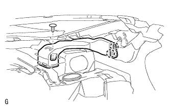
CONNECT AIR CONDITIONING TUBE AND ACCESSORY ASSEMBLY
-
Sufficiently apply compressor oil to 2 new O-rings and the fitting surface of the tube.
Compressor oil ND-OIL 11 or equivalent -
Install the 2 O-rings to the air conditioning tube and accessory assembly.
-
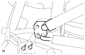
Install the air conditioning tube and accessory assembly with the 2 bolts.
- Torque:
- 9.8 N*m { 100 kgf*cm, 87 in.*lbf }
-
Install the No. 4 cooling unit packing as shown in the illustration.
-
Remove peeling paper A and attach the packing starting from the marking on the block joint.
-
Pull peeling paper B through the space between the duct and block joint and install the packing.
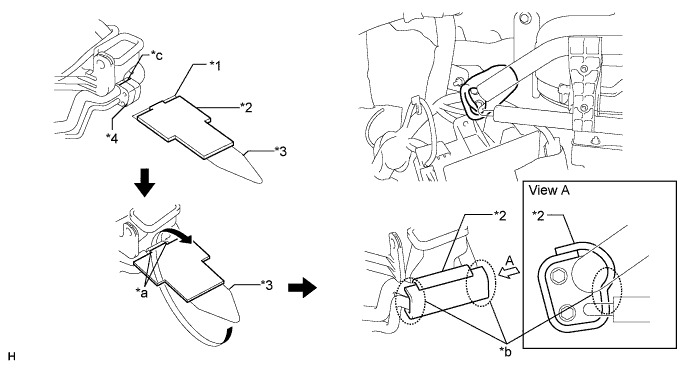
Text in Illustration *1 Peeling Paper A *2 No. 4 Cooling Unit Packing *3 Peeling Paper B *4 Block Joint *a Align the 2 edges of the packing with the edges of the block joint *b Be sure to securely attach the packing in these areas *c Marking - -
-
-
-
INSTALL NO. 2 COOLER AIR DUCT
-
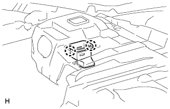
Attach the 2 claws to install the No. 2 cooler air duct.
-
-
INSTALL NO. 1 COOLER AIR DUCT
-
Attach the 2 claws to install the No. 1 cooler air duct.
-
-
INSTALL REAR NO. 4 AIR DUCT
-
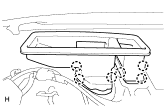
Attach the 6 claws to install the rear No. 4 air duct.
-
-
INSTALL REAR NO. 5 AIR DUCT
-
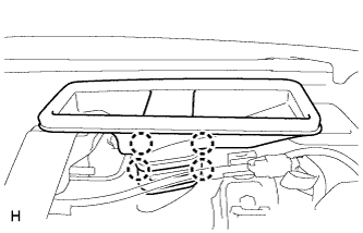
Attach the 4 claws to install the rear No. 5 air duct.
-
-
INSTALL NO. 2 ROOF SIDE AIR DUCT LH
-
Attach the 2 claws to install the No. 2 roof side air duct LH.
-
Install the clip.
-
-
INSTALL NO. 2 ROOF SIDE AIR DUCT RH
-
Attach the 2 claws to install the No. 2 roof side air duct RH.
-
Install the clip.
-
-
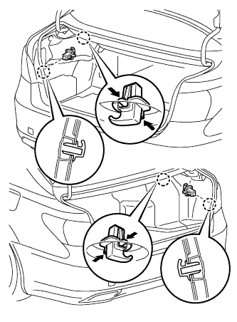
INSTALL LUGGAGE COMPARTMENT TRIM COVER ASSEMBLY RH
-
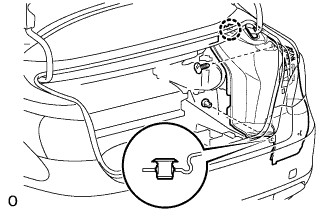
Install the luggage compartment trim cover assembly RH with the claw and 2 clips.
-
-
INSTALL LUGGAGE COMPARTMENT TRIM COVER ASSEMBLY LH
-
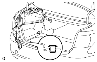
Install the luggage compartment trim cover assembly LH with the claw and 2 clips.
-
-
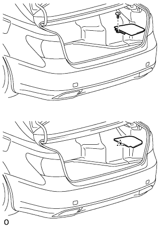
INSTALL REAR FLOOR FINISH PLATE
-
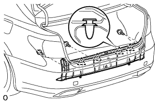
Attach the 4 clips to install the rear floor finish plate.
-
Install the 3 clips.
-
-
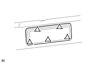
INSTALL FRONT LUGGAGE COMPARTMENT TRIM COVER
-
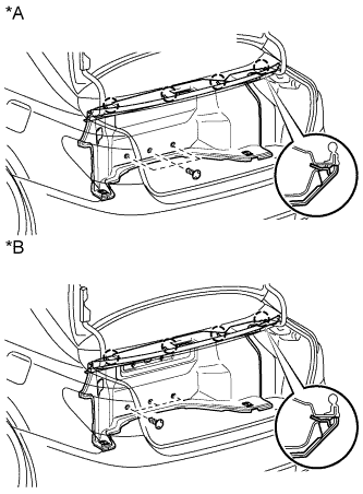
Text in Illustration *A w/o Rear Cooler *B w/ Rear Cooler Attach the 4 claws to install the front luggage compartment trim cover.
-
Install the 3 clips.
-
-
INSTALL NO. 1 LUGGAGE COMPARTMENT LIGHT ASSEMBLY
-
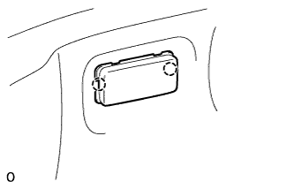
Connect the connector.
-
Attach the 2 claws to Install the No. 1 luggage compartment light assembly.
-
-
INSTALL DECK TRIM SIDE BOARD RH
-
Text in Illustration *A w/ Spare Tire *B w/o Spare Tire w/ Spare Tire:
-
Install the deck trim side board RH with the clip.
-
-
w/o Spare Tire:
-
Attach the clip to install the deck trim side board RH.
-
-
-
INSTALL ROPE HOOK ASSEMBLY
-
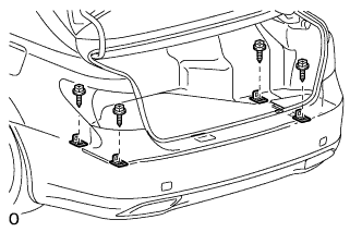
Install the 4 rope hook assemblies with the 4 bolts.
-
-
INSTALL ROPE HOOK
-
Install the 4 rope hooks.
-
-
INSTALL NO. 1 COOLER COVER
-
Attach the 5 clips to install the No. 1 cooler cover.
-
-
INSTALL PACKAGE TRAY TRIM PANEL ASSEMBLY
-
Connect the solar sensor connector.
-
except 4-Passenger with Ottoman:
Pass the 3 rear seat belt floor anchors through the package tray trim panel assembly.
-
for 4-Passenger with Ottoman:
Pass the 2 rear seat belt floor anchors through the package tray trim panel assembly.
-
Insert the rear part of the package tray trim panel assembly into the rear sunshade assembly.
-
Attach the 2 clips to install the package tray trim panel assembly.
-
except 4-Passenger with Ottoman:
Attach the 4 claws to install the 3 belt guides.
-
for 4-Passenger with Ottoman:
Attach the 4 claws to install the 2 belt guides.
-
-
INSTALL INNER ROOF SIDE GARNISH LH
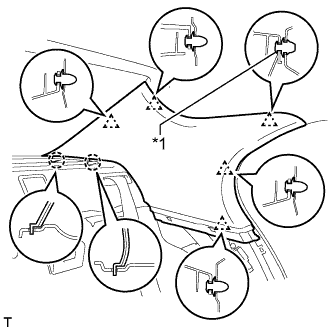
Text in Illustration *1 Clip A
-
Install a new clip A to the inner roof side garnish LH.
-
Attach the 2 claws and 5 clips to install the inner roof side garnish LH.
-
-
INSTALL INNER ROOF SIDE GARNISH RH
Tech Tips
Use the same procedure described for the LH side.
-
INSTALL REAR SEAT SIDE GARNISH LH
-
Attach the 6 claws to install the rear seat side garnish LH.
-
-
INSTALL REAR SEAT SIDE GARNISH RH
Tech Tips
Use the same procedure described for the LH side.
-
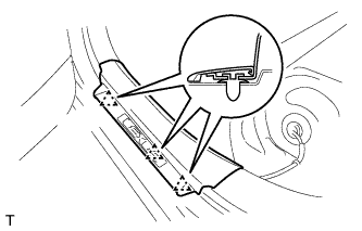
INSTALL REAR DOOR SCUFF PLATE LH
-
Attach the 3 clips.
-
Attach the 7 claws to install the rear door scuff plate LH.
-
-
INSTALL REAR DOOR SCUFF PLATE RH
Tech Tips
Use the same procedure described for the LH side.
-
INSTALL REAR SEAT ASSEMBLY
for Power Seat: Click here
for Ottoman: Click here
-
CONNECT CABLE TO AUXILIARY BATTERY NEGATIVE TERMINAL
Note
When disconnecting the cable, some systems need to be initialized after the cable is reconnected Click here.
-
INSTALL BATTERY SERVICE HOLE COVER LH
-

Text in Illustration *A for Standard *B for Ottoman Attach the battery service hole cover LH with the clip and fastening tape.
-
-
INSTALL DECK TRIM SIDE BOARD LH (w/o Spare Tire)
-

Attach the 2 clips to install the deck trim side board LH.
-
-
INSTALL DECK BOARD ASSEMBLY (w/o Spare Tire)

-
INSTALL LUGGAGE COMPARTMENT MAT SUB-ASSEMBLY (w/ Spare Tire)

-
ADD COMPRESSOR OIL
-
When performing work on air conditioning parts, follow the oil guidelines below in order to protect the cooler compressor.
Part and Condition Oil Level (cc) Work Procedure Compressor replacement -100 to -120 Drain oil from new compressor Condenser replacement 35 to 55 Fill oil into replacement part Evaporator replacement 40 to 60 A/C pipe replacement High pressure 5 to 25 Low pressure When discharging refrigerant gas quickly 30 to 50 While applying vacuum, use manifold gauge to fill oil from low pressure side valve
-
-
CHARGE REFRIGERANT
-
Perform vacuum purging using a vacuum pump or appropriate equipment.
-
Charge the air conditioning system with refrigerant.
Refrigerant type HFC-134a (R134a) 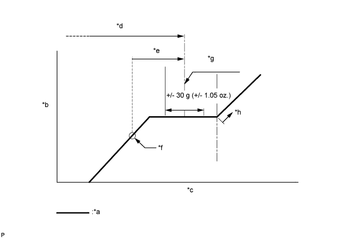
Text in Illustration *a Sub-cool System *b High Pressure *c Refrigerant Amount *d Standard charge amount *e Charge additional 100 g (3.5 oz.) *f Point where bubbles disappear *g Mean value in proper range *h Overcharged Standard charge amount 810 to 870 g (28.6 to 30.7 oz.) - SST
- 09985-20010 ( 09985-02010, 09985-02050, 09985-02060, 09985-02070, 09985-02080, 09985-02090, 09985-02110, 09985-02130, 09985-02140, 09985-02150 )
Note
-
Do not turn the A/C switch on before charging the air conditioning system with refrigerant. Doing so may cause the compressor to work without refrigerant, resulting in overheating of the compressor.
-
The refrigerant amount should be checked by quantity (weight).
Tech Tips
Make sure that sufficient refrigerant is available to recharge the system when using a refrigerant recovery unit. Refrigerant recovery units are not always able to recover 100% of the refrigerant from an air conditioning system.
-
-
WARM UP ENGINE
-
Keep the A/C switch on for at least 2 minutes to warm up the compressor.
Note
To prevent damage to the compressor, be sure to warm up the compressor when turning the air conditioning on after removing and installing air conditioning system lines (including the compressor).
-
-
CHECK FOR REFRIGERANT GAS LEAK
-
After recharging the air conditioning system with refrigerant, check for refrigerant leaks using a halogen leak detector.
-
Carry out the test under the following conditions:
-
Power switch off.
-
Secure good ventilation (the halogen leak detector may react to volatile gases which are not refrigerant, such as gasoline vapor and exhaust gas).
-
Repeat the inspection 2 or 3 times.
-
Measure the pressure to make sure that there is some refrigerant remaining in the air conditioning system (pressure when the compressor is off: approx. 392 to 588 kPa (3.9 to 5.9 kgf/cm2, 57 to 85 psi)).
-
-
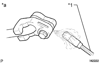
Text in Illustration *1 Halogen Leak Detector *a Check for Leak Using a halogen leak detector, check for refrigerant leaks from the air conditioning system.
-
If a refrigerant leak is not detected from the drain hose, remove the blower motor control from the cooling unit. Insert the halogen leak detector sensor into the unit and check for a leak.
-
Disconnect the pressure sensor connector and leave it for approximately 20 minutes. Bring the halogen leak detector close to the pressure sensor and check for a leak.
Tech Tips
When checking for leaks, the presence of oily dirt at a joint can indicate a leak.
-
-
CHECK SRS WARNING LIGHT