AIR CONDITIONING UNIT REMOVAL

Tech Tips
-
Use the same procedure for RHD and LHD vehicles.
-
The procedure listed below is for LHD vehicles.
-
RECOVER REFRIGERANT FROM REFRIGERATION SYSTEM
-
Turn the power switch on (READY).
-
Turn the A/C switch on.
-
Operate the air conditioning with a set temperature of 25°C (77°F) and the blower at low for 10 minutes to circulate the refrigerant. This causes most of the compressor oil from the various components of the air conditioning system to collect in the air conditioning compressor.
-
Turn the power switch off.
-
Recover the refrigerant from the air conditioning system using a refrigerant recovery unit.
-
-
REMOVE LUGGAGE COMPARTMENT MAT SUB-ASSEMBLY (w/ Spare Tire)

-
REMOVE DECK BOARD ASSEMBLY (w/o Spare Tire)

-
REMOVE DECK TRIM SIDE BOARD LH (w/o Spare Tire)
-

Detach the 2 clips and remove the deck trim side board LH.
-
-
REMOVE BATTERY SERVICE HOLE COVER LH
-

Text in Illustration *A for Standard *B for Ottoman *1 Fastening Tape Detach the clip, fastening tape and remove the battery service hole cover LH.
-
-
PRECAUTION
Note
After turning the power switch off, waiting time may be required before disconnecting the cable from the battery terminal. Therefore, make sure to read the disconnecting the cable from the battery terminal notice before proceeding with work Click here.
-
DISCONNECT CABLE FROM AUXILIARY BATTERY NEGATIVE TERMINAL
CAUTION:
Wait at least 90 seconds after disconnecting the cable from the negative (-) auxiliary battery terminal to disable the SRS system.
Note
When disconnecting the cable, some systems need to be initialized after the cable is reconnected Click here.
-
DISCONNECT SUCTION TUBE SUB-ASSEMBLY B
-
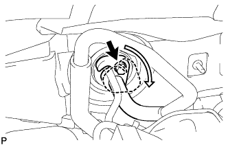
Remove the bolt and turn the hook connector clockwise.
-
Disconnect the suction tube sub-assembly B.
Note
-
Do not use a screwdriver or similar tool to disconnect the tube.
-
Seal the opening of the disconnected parts using vinyl tape to prevent moisture and foreign matter from entering them.
-
-
Remove the O-ring from the suction tube sub-assembly B.
-
-
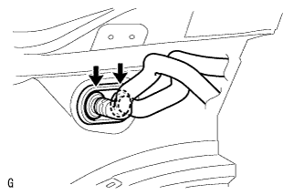
DISCONNECT COOLER REFRIGERANT LIQUID PIPE A
-
Disconnect the cooler refrigerant liquid pipe A.
Note
-
Do not use a screwdriver or similar tool to disconnect the tube.
-
Seal the opening of the disconnected parts using vinyl tape to prevent moisture and foreign matter from entering them.
-
-
Remove the O-ring from the cooler refrigerant liquid pipe A.
-
-
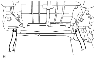
DISCONNECT INLET HEATER WATER HOSE
-
Using pliers, grip the claws of the clip and slide the clip.
-
Disconnect the inlet heater water hose.
Note
Prepare a drain pan or cloth in case the coolant leaks.
-
-
DISCONNECT OUTLET HEATER WATER HOSE
Tech Tips
Disconnection of the outlet heater water hose is the same as for the inlet heater water hose.
-
REMOVE INSTRUMENT PANEL SAFETY PAD SUB-ASSEMBLY
-
REMOVE NO. 1 AIR DUCT SUB-ASSEMBLY
-
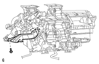
Remove the bolt.
-
Detach the 2 claws and remove the No. 1 air duct sub-assembly.
-
-
REMOVE NO. 2 AIR DUCT SUB-ASSEMBLY
-
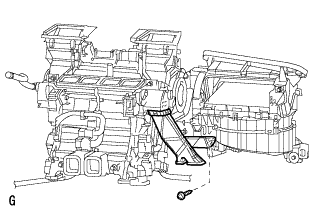
Remove the screw.
-
Detach the 2 claws and remove the No. 2 air duct sub-assembly.
-
-
REMOVE STEERING COLUMN ASSEMBLY
-
DISCONNECT COOLER UNIT DRAIN HOSE
-
Disconnect the 2 cooler unit drain hoses.
-
-
REMOVE WINDSHIELD WIPER MOTOR ASSEMBLY
-
REMOVE INSTRUMENT PANEL REINFORCEMENT ASSEMBLY
-
Disconnect the clamps, connectors and wire harness.
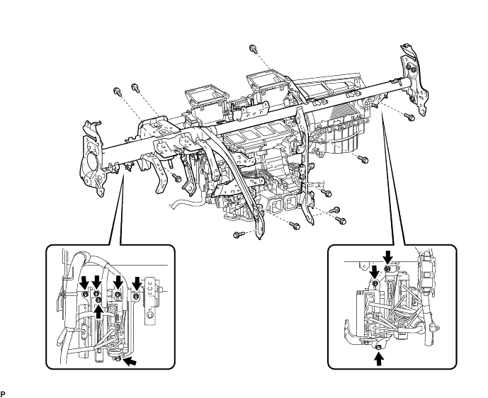
-
Remove the bolts and nuts, and disconnect the ground wire and junction block.
-
Remove the 9 bolts and 2 screws.
-
Remove the 6 instrument panel safety pad caps.
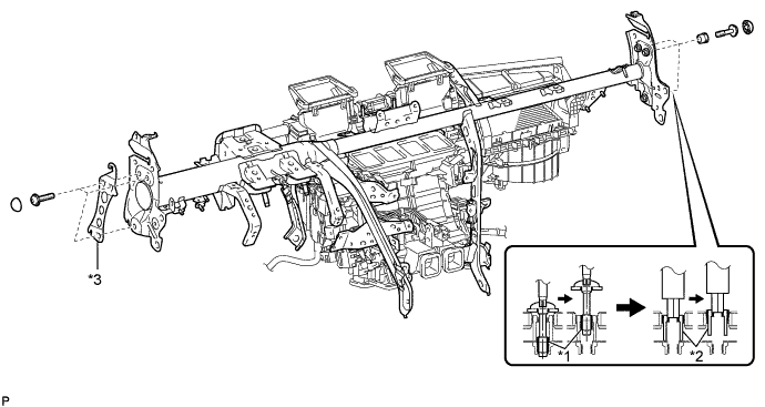
Text in Illustration *1 "TORX" Bolt *2 Collar *3 No. 1 Instrument Panel Spacer - - -
Using a T40 "TORX" socket wrench, remove the 6 "TORX" bolts.
Tech Tips
The "TORX" bolts on the passenger side can be removed with the collar for adjustment.
-
Passenger side:
Using a 12 mm hexagon wrench, remove the 3 collars.
-
Remove the instrument panel reinforcement with the No. 1 instrument panel spacer.
-
-
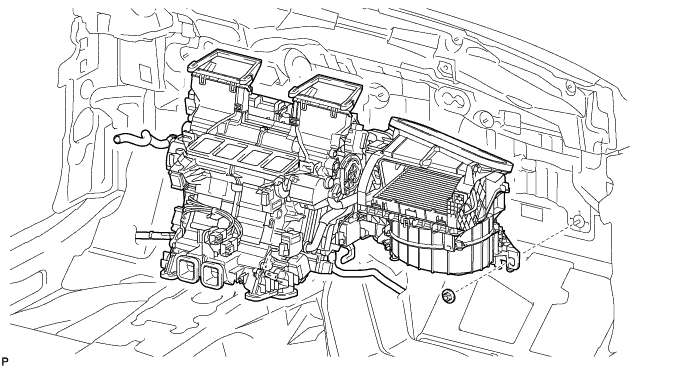
REMOVE AIR CONDITIONING UNIT
-
Remove the nut and air conditioning unit.
-