AIR CONDITIONING SYSTEM IG Power Source Circuit
DESCRIPTION
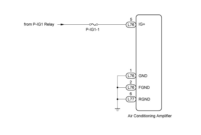
The main power source is supplied to the air conditioning amplifier when the power switch is ON (IG).
The power source is used for operating the air conditioning amplifier and servo motor, etc.
WIRING DIAGRAM
INSPECTION PROCEDURE
Tech Tips
Start the engine before inspection. Check the P-IG1 relay or battery if the smart access system with push-button start does not start.
PROCEDURE
-
INSPECT FUSE (P-IG1-1)
-
Remove the P-IG1-1 fuse from the passenger side junction block.
-
Measure the resistance according to the value(s) in the table below.
Standard resistance Tester Connection Condition Specified Condition P-IG1-1 fuse Always Below 1 Ω
NG 
REPLACE FUSE
OK 
-
-
CHECK AIR CONDITIONING AMPLIFIER (IG+ VOLTAGE)
-
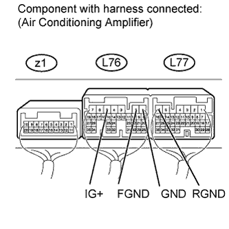
Remove the air conditioning amplifier with its connectors still connected Click here.
-
Measure the voltage according to the value(s) in the table below.
Standard voltage Tester Connection Condition Specified Condition L76-5 (IG+) - L76-1 (GND) Power switch ON (IG) 11 to 14 V L76-5 (IG+) - L76-2 (FGND) L76-5 (IG+) - L77-6 (RGND)
NG 
CHECK HARNESS AND CONNECTOR (AIR CONDITIONING AMPLIFIER - BATTERY AND BODY GROUND) Click here
OK 
PROCEED TO NEXT CIRCUIT INSPECTION SHOWN IN PROBLEM SYMPTOMS TABLE Click here
-
-
CHECK HARNESS AND CONNECTOR (AIR CONDITIONING AMPLIFIER - BATTERY AND BODY GROUND)
-
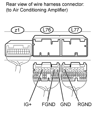
Disconnect the L76 and L77 air conditioning amplifier connectors.
-
Measure the voltage according to the value(s) in the table below.
Standard voltage Tester Connection Condition Specified Condition L76-5 (IG+) - Body ground Power switch OFF Below 1 V Power switch ON (IG) 11 to 14 V -
Measure the resistance according to the value(s) in the table below.
Standard resistance Tester Connection Condition Specified Condition L76-1 (GND) - Body ground Always Below 1 Ω L76-2 (FGND) - Body ground L77-6 (RGND) - Body ground
NG
REPAIR OR REPLACE HARNESS OR CONNECTOR
OK
PROCEED TO NEXT CIRCUIT INSPECTION SHOWN IN PROBLEM SYMPTOMS TABLE Click here
-