AIR CONDITIONING SYSTEM, Diagnostic DTC:B1498/98

| DTC Code | DTC Name |
|---|---|
| B1498/98 | Communication Malfunction (A/C Inverter Local) |
DESCRIPTION
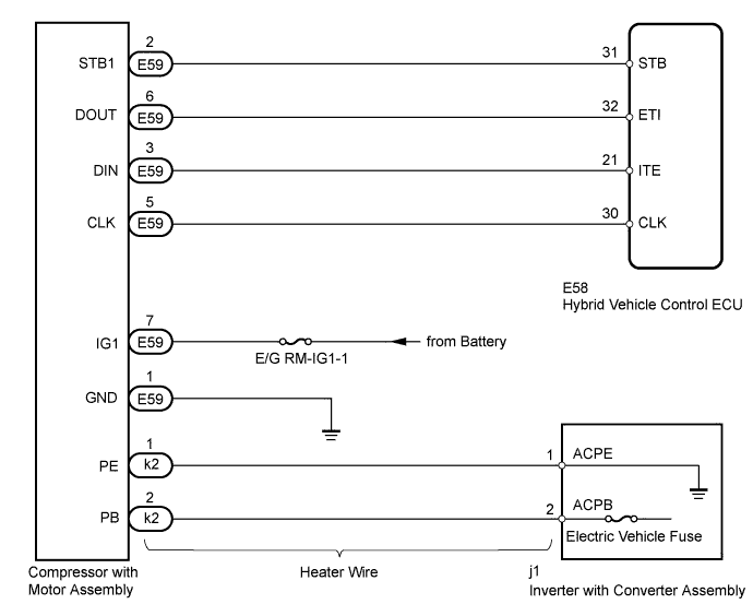
The hybrid vehicle control ECU and compressor with motor assembly transmit information to one another via the communication line. Compressor control is stopped and the DTC is output if communication information is cut off or abnormal information occurs.
The DTC is also detected if high-voltage power supplied from the inverter with converter assembly to the compressor control circuit is shut off.
The output DTC is memorized as a past DTC.
Note
Depending on the timing of the power supply to the 12 V power supply circuit and high-voltage circuit when the power switch is turned on (READY), an abnormal information signal may be output, causing this DTC to be stored. If the output DTC is a code that was memorized in the past, check the fuses and wire harnesses. If there is no malfunction, erase the DTC.
| DTC No. | DTC Detection Condition | Trouble Area |
|---|---|---|
| B1498/98 |
|
|
WIRING DIAGRAM
INSPECTION PROCEDURE
CAUTION:
-
When troubleshooting B1498/98, be sure to wrap tools with electrical tape. (It is very dangerous if high voltage is shorted to ground through tools.)
-
Wear electrically insulated gloves and pull out the service plug grip before inspection as procedures may require disconnecting high-voltage connectors. Be sure to carry the removed service plug grip because other workers may install it by mistake.
-
Be sure to carry the removed service plug grip because other workers may install it by mistake.
-
Do not touch the high-voltage connectors or terminals for 10 minutes after the service plug grip is removed.
Note
The hybrid control system and air conditioning system output DTCs separately. Inspect DTCs following the flowchart for the hybrid control system first if any DTCs from those systems are output simultaneously.
Tech Tips
-
Waiting for at least 10 minutes is required to discharge the high-voltage capacitor inside the inverter with converter assembly.
-
When measuring insulation resistance using a megohmmeter, measure the resistance while jiggling the high-voltage wire harness.
-
When measuring insulation resistance using a megohmmeter, set the megohmmeter to 500 V.
PROCEDURE
-
CHECK DTC (HYBRID CONTROL SYSTEM)
-
Check if DTCs for the hybrid control system are output using the intelligent tester Click here.
Result Result Proceed to DTC is not output A Only DTC P3108-535 is output DTCs other than P3108-535 are output B
B 
GO TO HYBRID CONTROL SYSTEM Click here
A 
-
-
CHECK DTC (CAN COMMUNICATION SYSTEM)
-
Check if DTCs for the CAN communication system are output using the intelligent tester.
-
for LHD: Click here.
-
for RHD: Click here.
Result Result Proceed to CAN DTC is not output A CAN DTC is output (for LHD) B CAN DTC is output (for RHD) C -
B
GO TO CAN COMMUNICATION SYSTEM Click here
C
GO TO CAN COMMUNICATION SYSTEM Click here
A
-
-
INSPECT FUSE (E/G RM-IG1-1)
-
Remove the E/G RM-IG1-1 fuse from the engine room No. 2 relay block.
-
Measure the resistance according to the value(s) in the table below.
Standard resistance Tester Connection Condition Specified condition E/G RM-IG1-1 fuse Always Below 1 Ω
NG
REPLACE FUSE
OK
-
-
CHECK HARNESS AND CONNECTOR (COMPRESSOR WITH MOTOR ASSEMBLY - BODY GROUND)
-
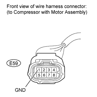
Disconnect the E59 compressor with motor assembly connector.
CAUTION:
Do not disconnect the connector on the high-voltage side.
-
Measure the resistance according to the value(s) in the table below.
Standard resistance Tester Connection Condition Specified Condition E59-1 (GND) - Body ground Always Below 1 Ω
NG
REPAIR OR REPLACE HARNESS OR CONNECTOR
OK
-
-
CHECK HARNESS AND CONNECTOR (COMPRESSOR WITH MOTOR ASSEMBLY -BATTERY)
-
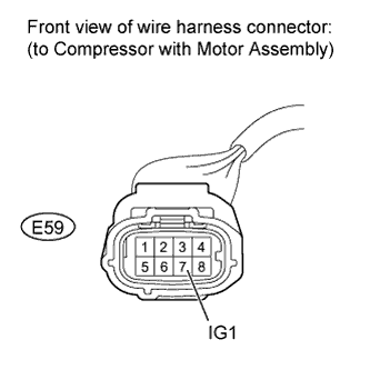
Disconnect the E59 compressor with motor assembly connector.
-
Measure the voltage according to the value(s) in the table below.
Standard voltage Tester Connection Condition Specified Condition E59-7 (IG1) - Body ground Power switch on (IG) 11 to 14 V Power switch off Below 1 V
NG
REPAIR OR REPLACE HARNESS OR CONNECTOR
OK
-
-
CHECK HARNESS AND CONNECTOR (HYBRID VEHICLE CONTROL ECU - COMPRESSOR WITH MOTOR ASSEMBLY)
-
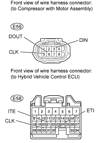
Disconnect the E58 hybrid vehicle control ECU connector.
-
Disconnect the E59 compressor with motor assembly connector.
-
Measure the resistance according to the value(s) in the table below.
Standard resistance Tester Connection Condition Specified Condition E59-5 (CLK) - E58-30 (CLK) Always Below 1 Ω E59-3 (DIN) - E58-21 (ITE) E59-6 (DOUT) - E58-32 (ETI) E59-5 (CLK) - Body ground Always 10 kΩ or higher E59-3 (DIN) - Body ground E59-6 (DOUT) - Body ground
NG
REPAIR OR REPLACE HARNESS OR CONNECTOR
OK
-
-
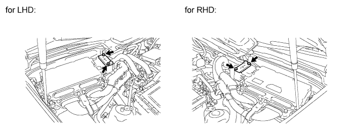
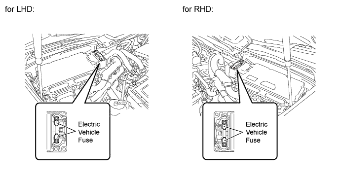
INSPECT INVERTER WITH CONVERTER ASSEMBLY (ELECTRIC VEHICLE FUSE)
CAUTION:
Be sure to wear insulated gloves.
-
Turn the power switch off.
-
Remove the service plug grip. Click here
Note
After removing the service plug grip, do not turn the power switch on (READY) unless instructed by the repair manual because this may cause a malfunction.
-
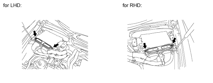
Remove the inverter terminal cover from the inverter with converter assembly.
-
for LHD: Click here.
-
for RHD: Click here.
Note
Lift the inverter terminal cover horizontally so that it does not tilt. Failure to do so may break the inverter cover guide pins.
-
-
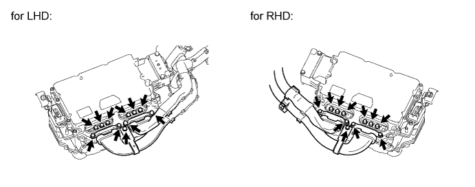
Disconnect the motor cable and generator cable from the inverter with converter assembly.
-
Remove the connector cover from the inverter with converter assembly.
-
for LHD: Click here.
-
for RHD: Click here.
Tech Tips
Make sure that no foreign objects have entered or contaminated the inverter with converter assembly.
-
-
Using a megohmmeter set to 500 V, measure the resistance according to the value(s) in the table below.
Note
Be sure to set the megohmmeter to 500 V when performing this test. Using a setting higher than 500 V can result in damage to the component being inspected.
Standard resistance Tester Connection Switch Condition Specified Condition Electric vehicle fuse - Body ground Power switch off 1.0 MΩ or higher Result Result Proceed to OK A NG (for LHD) B NG (for RHD) C
B
REPLACE ELECTRIC VEHICLE FUSE Click here
C
REPLACE ELECTRIC VEHICLE FUSE Click here
A
-
-
INSPECT HEATER WIRE
-
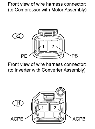
Disconnect the k2 and j1 heater wire connectors.
CAUTION:
Be sure to wear insulated gloves.
-
Measure the resistance according to the value(s) in the table below.
Standard resistance Tester Connection Condition Specified Condition k2-1 (PE) - j1-1 (ACPE) Always Below 1 Ω k2-2 (PB) - j1-2 (ACPB) k2-1 (PE) - k2-2 (PB) Always 10 kΩ or higher
NG
REPLACE HEATER WIRE Click here
OK
-
-
REPLACE COMPRESSOR WITH MOTOR ASSEMBLY
CAUTION:
Be sure to wear insulated gloves.
-
Temporarily replace the compressor with motor assembly with a new or normally functioning one Click here.
NEXT
-
-
RECHECK DTC
-
Check if DTCs for the air conditioning system are output using the intelligent tester Click here.
Result Result Proceed to DTC is not output A DTC B1498/98 is output B
NG
REPLACE HYBRID VEHICLE CONTROL ECU Click here
OK 
END (COMPRESSOR WITH MOTOR ASSEMBLY IS DEFECTIVE)
-