DESCRIPTION
The inverter activation signal is sent to the compressor with motor assembly from the hybrid vehicle control ECU. Compressor control is stopped and the DTC is output if there is an open or short in the signal circuit.
| DTC No. | DTC Detection Condition | Trouble Area |
|---|---|---|
| B1473/73 | Open or short in A/C inverter start-up signal system |
|
INSPECTION PROCEDURE
PROCEDURE
- Click here
CHECK DTC (CAN COMMUNICATION SYSTEM)
-
Use the intelligent tester to check if the CAN communication system is functioning normally.
Table 1. Result Result Proceed to CAN DTC is not output A CAN DTC is output (for LHD) B CAN DTC is output (for RHD) C
-
- Click here
CHECK DTC
-
Check if DTCs for the air conditioning system and the hybrid control system are output using the intelligent tester.
Table 2. Result Result Proceed to Only DTC B1473 is output A DTCs B1473 and P3108-538 are output simultaneously (B1498 is not output) DTCs B1473 and B1498 are output simultaneously (P3108-538 is not output) B DTCs B1473, B1498 and P3108-538 are output simultaneously DTCs other than P3108-538 are output for hybrid control system C
-
- Click here
CHECK HARNESS AND CONNECTOR (HYBRID VEHICLE CONTROL ECU - COMPRESSOR WITH MOTOR ASSEMBLY)
-
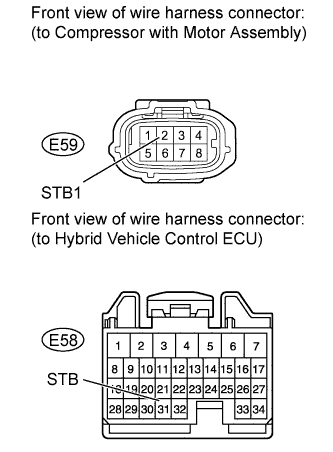
Disconnect the E58 hybrid vehicle control ECU connector.
-
Disconnect the E59 compressor with motor assembly connector.
CAUTION:Do not disconnect the connector on the high-voltage side.
-
Measure the resistance according to the value(s) in the table below.
Standard resistance Tester Connection Condition Specified Condition E59-2 (STB1) - E58-31 (STB) Always Below 1 Ω E58-31 (STB) - Body ground Always 10 kΩ or higher
- OKClick here
- NGClick here
-
- Click here
INSPECT COMPRESSOR WITH MOTOR ASSEMBLY
-
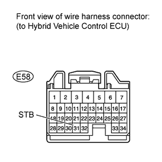
Disconnect the E58 hybrid vehicle control ECU connector.
-
Reconnect the E59 compressor with motor assembly connector.
-
Measure the voltage according to the value(s) in the table below.
Standard voltage Tester Connection Condition Specified Condition E58-31 (STB) - Body ground Power switch ON (IG) 11 to 14 V Power switch OFF Below 1 V
- OKClick here
- NGClick here
-
- Click here
GO TO CAN COMMUNICATION SYSTEMClick here
- Click here
GO TO DTC B1498/98Click here
- Click here
GO TO HYBRID CONTROL SYSTEMClick here
- Click here
REPAIR OR REPLACE HARNESS OR CONNECTOR
- Click here
REPLACE COMPRESSOR WITH MOTOR ASSEMBLYClick here
- Click here
REPLACE HYBRID VEHICLE CONTROL ECUClick here
- Click here
GO TO CAN COMMUNICATION SYSTEMClick here