AIR CONDITIONING SYSTEM, Diagnostic DTC:B14A4

| DTC Code | DTC Name |
|---|---|
| B14A4 | Solar Sensor Short Circuit(Rear Driver Side) |
DESCRIPTION
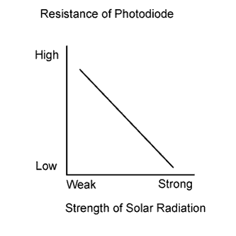
The rear solar sensor is installed on the package tray trim panel. It detects sunlight to control air conditioning AUTO mode. The output voltage from the rear solar sensor varies in accordance with the amount of sunlight. When the sunlight increases, the output voltage increases. As the sunlight decreases, the output voltage decreases. The luggage room junction block (rear junction block ECU) sends the read signal to the air conditioning amplifier via the CAN communication line.
| DTC Code | DTC Detection Condition | Trouble Area |
|---|---|---|
| B14A4 | Short in rear solar sensor circuit |
|
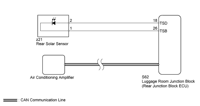
WIRING DIAGRAM
INSPECTION PROCEDURE
Tech Tips
This circuit uses the CAN communication line. Before performing the inspection, check that the CAN communication system is functioning normally.
PROCEDURE
-
READ VALUE USING GTS (REAR SOLAR SENSOR)
-
Use the Data List to check if the driver side solar sensor is functioning properly.
Air Conditioner Tester Display Measurement Item/Range Normal Condition Diagnostic Note Rear Solar Sensor Rear solar sensor /
Min.: 0, Max.: 255
Rear solar sensor value increases as brightness increases - OK The display is as specified in the normal condition.
NG 
INSPECT REAR SOLAR SENSOR Click here
OK 
REPLACE AIR CONDITIONER AMPLIFIER Click here
-
-
INSPECT REAR SOLAR SENSOR
-
Remove the rear solar sensor Click here.
-
Inspect the rear solar sensor Click here.
NG 
REPLACE REAR SOLAR SENSOR Click here
OK 
-
-
CHECK HARNESS AND CONNECTOR (REAR SOLAR SENSOR - REAR JUNCTION BLOCK ECU)
-
Disconnect the z21 rear solar sensor connector.
-
Disconnect the S62 luggage room junction block (rear junction block ECU) connector.
-
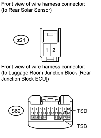
Measure the resistance according to the value(s) in the table below.
Standard resistance Tester Connection Condition Specified Condition z21-1 - S62-26 (TSB) Always Below 1 Ω z21-2 - S62-18 (TSD) Always Below 1 Ω S62-26 (TSB) - Body ground Always 10 kΩ or higher S62-18 (TSD) - Body ground Always 10 kΩ or higher
NG
REPAIR OR REPLACE HARNESS OR CONNECTOR
OK
REPLACE LUGGAGE ROOM JUNCTION BLOCK (REAR JUNCTION BLOCK ECU)
-