AIR CONDITIONING SYSTEM, Diagnostic DTC:B14A3

| DTC Code | DTC Name |
|---|---|
| B14A3 | Front Passenger Side Solar Sensor Short Circuit |
DESCRIPTION
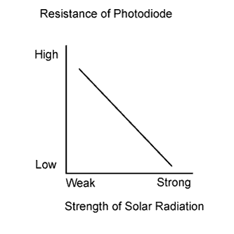
The automatic light control sensor is installed on the upper side of the instrument panel. It detects sunlight to control air conditioning AUTO mode. The output voltage from the automatic light control sensor varies in accordance with the amount of sunlight. When the sunlight increases, the output voltage increases. As the sunlight decreases, the output voltage decreases. The air conditioning amplifier detects changes in the output voltage from the automatic light control sensor.
| DTC Code | DTC Detection Condition | Trouble Area |
|---|---|---|
| B14A3 | Short in passenger side automatic light control sensor circuit |
|
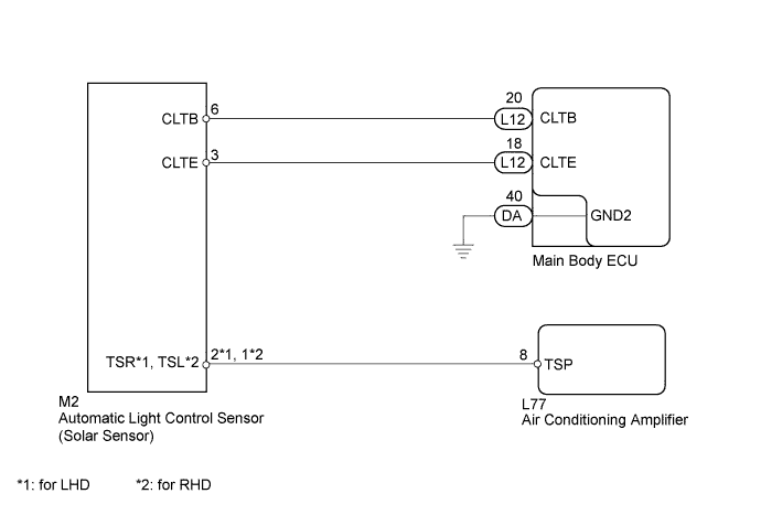
WIRING DIAGRAM
INSPECTION PROCEDURE
PROCEDURE
-
READ VALUE USING GTS (SOLAR SENSOR [P SIDE])
-
Use the Data List to check if the passenger side solar sensor is functioning properly.
Air Conditioner Tester Display Measurement Item/Range Normal Condition Diagnostic Note Solar Sensor (P Side) Front passenger side automatic light control sensor /
Min.: 0, Max.: 255
Front passenger side automatic light control sensor value increases as brightness increases - OK The display is as specified in the normal condition.
NG 
CHECK HARNESS AND CONNECTOR (POWER SOURCE CIRCUIT) Click here
OK 
REPLACE AIR CONDITIONING AMPLIFIER Click here
-
-
CHECK HARNESS AND CONNECTOR (POWER SOURCE CIRCUIT)
-
Disconnect the M2 automatic light control sensor connector.
-
Measure the resistance according to the value(s) in the table below.
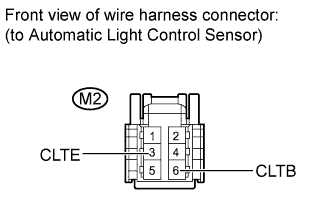
Standard resistance Tester Connection Condition Specified Condition M2-3 (CLTE) - Body ground Always Below 1 Ω -
Measure the voltage according to the value(s) in the table below.
Standard voltage Tester Connection Switch Condition Specified Condition M2-6 (CLTB) - M2-3 (CLTE) Power switch ON (IG) 11 to 14 V M2-6 (CLTB) - M2-3 (CLTE) Power switch OFF Below 1 V
NG
CHECK HARNESS AND CONNECTOR (MAIN BODY ECU - AUTOMATIC LIGHT CONTROL SENSOR) Click here
OK 
-
-
CHECK HARNESS AND CONNECTOR (AUTOMATIC LIGHT CONTROL SENSOR - AIR CONDITIONING AMPLIFIER)
-
Disconnect the M2 automatic light control sensor connector.
-
Disconnect the L77 air conditioning amplifier connector.
-
Measure the resistance according to the value(s) in the table below.
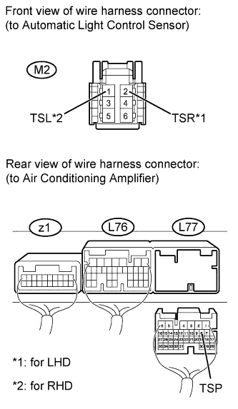
Standard resistance for LHD Tester Connection Condition Specified Condition L77-8 (TSP) - M2-2 (TSR) Always Below 1 Ω L77-8 (TSP) - Body ground Always 10 kΩ or higher for RHD Tester Connection Condition Specified Condition L77-8 (TSP) - M2-1 (TSL) Always Below 1 Ω L77-8 (TSP) - Body ground Always 10 kΩ or higher
NG 
REPAIR OR REPLACE HARNESS OR CONNECTOR
OK
-
-
INSPECT AUTOMATIC LIGHT CONTROL SENSOR (SOLAR SENSOR)
-
Remove the automatic light control sensor Click here.
-
Inspect the automatic light control sensor Click here.
NG
REPLACE AUTOMATIC LIGHT CONTROL SENSOR Click here
OK
REPLACE AIR CONDITIONING AMPLIFIER Click here
-
-
CHECK HARNESS AND CONNECTOR (MAIN BODY ECU - AUTOMATIC LIGHT CONTROL SENSOR)
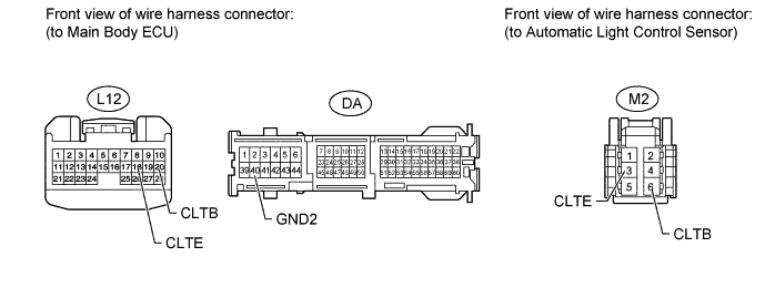
-
Disconnect the L12 and DA main body ECU connectors.
-
Disconnect the M2 automatic light control sensor connector.
-
Measure the resistance according to the value(s) in the table below.
Standard resistance Tester Connection Condition Specified Condition L12-20 (CLTB) - M2-6 (CLTB) Always Below 1 Ω L12-18 (CLTE) - M2-3 (CLTE) Always Below 1 Ω L12-20 (CLTB) - Body ground Always 10 kΩ or higher L12-18 (CLTE) - Body ground Always 10 kΩ or higher DA-40 (GND2) - Body ground Always Below 1 Ω
NG
REPAIR OR REPLACE HARNESS OR CONNECTOR
OK
REPLACE MAIN BODY ECU (DRIVER SIDE JUNCTION BLOCK)
-