AIR CONDITIONING SYSTEM, Diagnostic DTC:B1462/62

| DTC Code | DTC Name |
|---|---|
| B1462/62 | Room Humidity Sensor Circuit |
DESCRIPTION
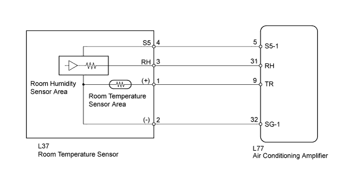
The room humidity sensor detects room humidity. The voltage of the room humidity sensor changes in accordance with room humidity. The air conditioning amplifier reads changes in the room humidity sensor.
The room humidity sensor is integrated with the room temperature sensor.
| DTC Code | DTC Detection Condition | Trouble Area |
|---|---|---|
| B1462/62 | Open or short in room humidity sensor circuit |
|
WIRING DIAGRAM
INSPECTION PROCEDURE
PROCEDURE
-
READ VALUE USING INTELLIGENT TESTER (HUMIDITY SENS)
-
Use the Data List to check if the room humidity sensor is functioning properly.
Air Conditioner Tester Display Measurement Item / Range Normal Condition Diagnostic Note Humidity Sensor Humidity Sensor /
Min.: 0%, Max.: 100%
Actual room humidity is displayed - OK The display is as specified in the normal condition.
NG 
CHECK WIRE HARNESS (ROOM TEMPERATURE SENSOR - A/C AMPLIFIER) Click here
OK 
REPLACE AIR CONDITIONING AMPLIFIER Click here
-
-
CHECK WIRE HARNESS (ROOM TEMPERATURE SENSOR - A/C AMPLIFIER)
-
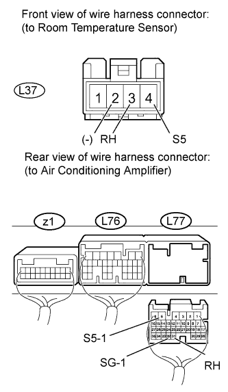
Disconnect the L37 room humidity sensor (room temperature sensor) connector.
-
Disconnect the L77 air conditioning amplifier connector.
-
Measure the resistance according to the value(s) in the table below.
Standard resistance Tester Connection Condition Specified Condition L37-3 (RH) - L77-31 (RH) Always Below 1 Ω L37-4 (S5) - L77-5 (S5-1) L37-2 (-) - L77-32 (SG-1) L77-32 (SG-1) - Body ground Always 10 kΩ or higher L77-31 (RH) - Body ground L77-5 (S5-1) - Body ground
NG 
REPAIR OR REPLACE HARNESS OR CONNECTOR
OK 
-
-
CHECK AIR CONDITIONING AMPLIFIER (S5-1 - SG-1 VOLTAGE)
-
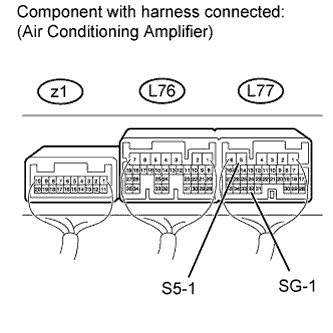
Remove the air conditioning amplifier with its connectors still connected.
-
Measure the voltage according to the value(s) in the table below.
Standard voltage Tester Connection Condition Specified Condition L77-5 (S5-1) - L77-32 (SG-1) Power switch ON (IG) 4.5 to 5.5 V Power switch OFF Below 1 V
NG
REPLACE AIR CONDITIONING AMPLIFIER Click here
OK
-
-
INSPECT ROOM TEMPERATURE SENSOR (ROOM HUMIDITY SENSOR)
-
Remove the room humidity sensor (room temperature sensor).
-
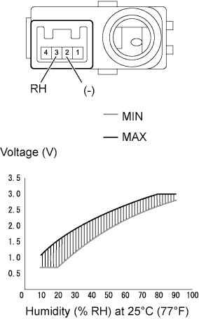
Measure the voltage according to the value(s) in the table below.
Standard voltage Tester Connection Humidity Condition Specified Condition 2 (-) - 3 (RH) 10% 0.70 to 1.08 V 20% 0.72 to 1.57 V 30% 1.13 to 1.95 V 40% 1.61 to 2.24 V 50% 1.99 to 2.46 V 60% 2.26 to 2.66 V 70% 2.48 to 2.85 V 80% 2.68 to 3.04 V 90% 2.87 to 3.05 V Note
-
Do not touch the humidity sensor as body heat will affect the inspection results. When performing the inspection, hold the sensor by its connector.
-
Allow the sensor to acclimate to the ambient temperature and humidity before performing the inspection.
-
The standard voltages in the table above are based on inspections performed when the ambient temperature is 25°C (77°F).
-
NG
REPLACE ROOM TEMPERATURE SENSOR Click here
OK
REPLACE AIR CONDITIONING AMPLIFIER Click here
-