AIR CONDITIONING SYSTEM, Diagnostic DTC:B1461/61

| DTC Code | DTC Name |
|---|---|
| B1461/61 | Emission Gas NOx Sensor Circuit |
DESCRIPTION
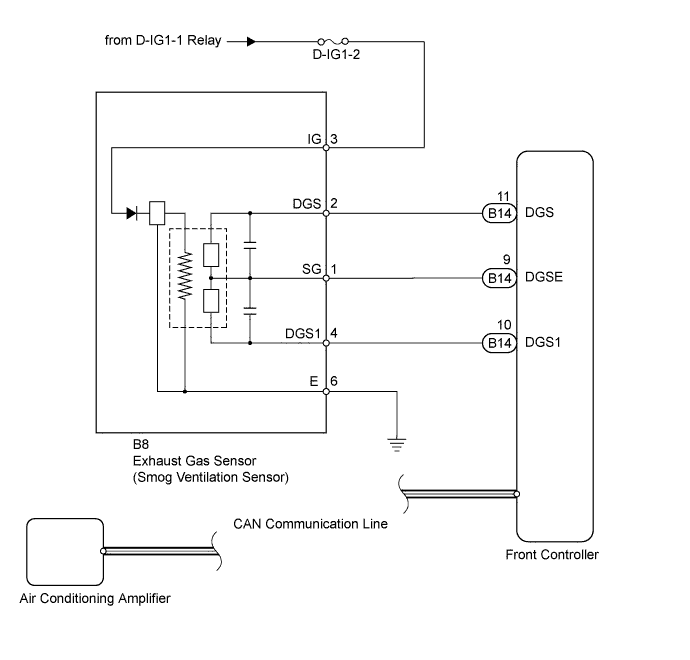
The exhaust gas sensor, which is installed on the front of the condenser, automatically changes to FRESH, FRESH / RECIRCULATION, or RECIRCULATION. The exhaust gas sensor detects NOx in the emission gas and transmits signals to the front controller.
The front controller sends the read signal to the air conditioning amplifier via the CAN communication line.
Tech Tips
This circuit uses the CAN communication line. Before performing the inspection, check that the CAN communication system is functioning normally.
| DTC Code | DTC Detection Condition | Trouble Area |
|---|---|---|
| B1461/61 | Open or short in emission gas sensor circuit (NOx) |
|
WIRING DIAGRAM
INSPECTION PROCEDURE
PROCEDURE
-
INSPECT FUSE (D-IG1-2)
-
Remove the D-IG1-2 fuse from the main body ECU (driver side junction block).
-
Measure the resistance according to the value(s) in the table below.
Standard resistance Tester Connection Condition Specified Condition D-IG1-2 fuse Always Below 1 Ω
NG 
REPLACE FUSE
OK 
-
-
READ VALUE USING INTELLIGENT TESTER (EMISSION GAS NOX SENSOR)
-
Use the Data List to check if the emission gas NOx sensor is functioning properly.
Air Conditioner Tester Display Measurement Item / Range Normal Condition Diagnostic Note Emission Gas Nox Sensor Emission gas NOx sensor/
Min.: 0, Max.: 255
Increases as the gas amount increases - OK The display is as specified in the normal condition.
NG 
CHECK HARNESS AND CONNECTOR (EXHAUST GAS SENSOR - BODY GROUND) Click here
OK 
REPLACE AIR CONDITIONING AMPLIFIER Click here
-
-
CHECK HARNESS AND CONNECTOR (EXHAUST GAS SENSOR - BODY GROUND)
-
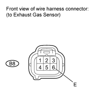
Disconnect the B8 exhaust gas sensor connector.
-
Measure the resistance according to the value(s) in the table below.
Standard resistance Tester Connection Condition Specified Condition B8-6 (E) - Body ground Always Below 1 Ω
NG
REPAIR OR REPLACE HARNESS OR CONNECTOR
OK
-
-
CHECK HARNESS AND CONNECTOR (EXHAUST GAS SENSOR - BATTERY)
-
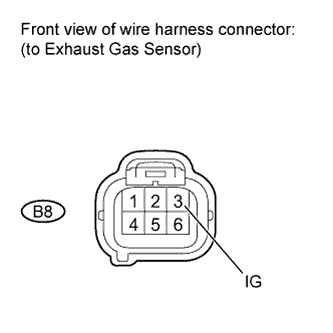
Disconnect the B8 exhaust gas sensor connector.
-
Measure the voltage according to the value(s) in the table below.
Standard voltage Tester Connection Condition Specified Condition B8-3 (IG) - Body ground Power switch ON (IG) 11 to 14 V Power switch OFF Below 1 V
NG
REPAIR OR REPLACE HARNESS OR CONNECTOR
OK
-
-
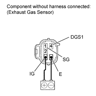
INSPECT EXHAUST GAS SENSOR
-
Remove the exhaust gas sensor Click here.
-
After applying battery voltage between terminals 3 (IG) and 6 (E) for more than 30 seconds, measure the resistance according to the value(s) in the table below.
Standard resistance Tester Connection Condition Specified Condition 1 (SG) - 4 (DGS1) 10 to 35°C
(50 to 95°F)
1.5 to 240 kΩ Tech Tips
When the sensor is exposed to the exhaust gas, the resistance increases.
NG
REPLACE EXHAUST GAS SENSOR Click here
OK
-
-
CHECK HARNESS AND CONNECTOR (EXHAUST GAS SENSOR - FRONT CONTROLLER)
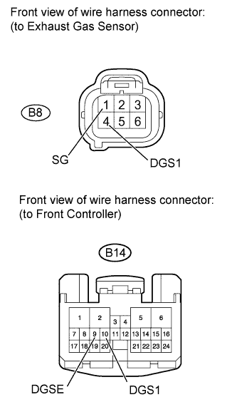
-
Disconnect the B8 exhaust gas sensor connector.
-
Disconnect the B14 front controller connector.
-
Measure the resistance according to the value(s) in the table below.
Standard resistance Tester Connection Condition Specified Condition B8-1 (SG) - B14-9 (DGSE) Always Below 1 Ω B8-4 (DGS1) - B14-10 (DGS1) B14-9 (DGSE) - Body ground Always 10 kΩ or higher B14-10 (DGS1) - Body ground
NG
REPAIR OR REPLACE HARNESS OR CONNECTOR
OK
REPLACE FRONT CONTROLLER
-