AIR CONDITIONING SYSTEM TERMINALS OF ECU

-
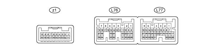
CHECK AIR CONDITIONING AMPLIFIER
-
Disconnect the L76, L77 and z1 air conditioning amplifier connectors.
-
Measure the voltage and resistance according to the value(s) in the table below.
Terminal No. (Symbol) Wiring Color Terminal Description Condition Specified Condition L76-1 (GND) - Body ground W-B - Body ground Ground Always Below 1 Ω L76-2 (FGND) - Body ground W-B - Body ground Ground Always Below 1 Ω L76-5 (IG+) - L76-1 (GND) V - W-B Ignition power supply Power switch ON (IG) 11 to 14 V Power switch OFF Below 1 V L76-6 (+B1) - L76-1 (GND) L - W-B Auxiliary battery power supply Always 11 to 14 V L76-7 (+B2) - L76-1 (GND) L - W-B Auxiliary battery power supply Always 11 to 14 V L76-12 (BRRG) - Body ground G - Body ground Ground for BUS IC (for Rear) Always Below 1 Ω L76-14 (BRRB) - L76-12 (BRRG) L - G Power supply for BUS IC (for Rear) Power switch ON (IG) 11 to 14 V L77-6 (RGND) - Body ground W-B - Body ground Ground Always Below 1 Ω L77-32 (SG-1) - Body ground L - Body ground Ground for room temperature sensor (for Front) Always Below 1 Ω z1-1 (BFLG) - Body ground - Ground for BUS IC (for Front) Always Below 1 Ω z1-3 (BFLB) - z1-1 (BFLG) - Power supply for BUS IC (for Front) Power switch ON (IG) 11 to 14 V z1-6 (SG-6) - Body ground - Ground for evaporator temperature sensor Always Below 1 Ω z1-8 (BFRG) - Body ground - Ground for BUS IC (for Front) Always Below 1 Ω z1-10 (BFRB) -z1-8 (BFRG) - Power supply for BUS IC (for Front) Power switch ON (IG) 11 to 14 V z1-11 (BUSG) - Body ground - Ground for BUS IC (for Front) Always Below 1 Ω z1-13 (BUSB) -z1-11 (BUSG) - Power supply for BUS IC (for Front) Power switch ON (IG) 11 to 14 V -
Reconnect the L76, L77 and z1 air conditioning amplifier connectors.
-
Measure the voltage, resistance and waveform according to the value(s) in the table below.
Terminal No. (Symbol) Wiring Color Terminal Description Condition Specified Condition L76-3 (BLW) - L76-1 (GND) W - W-B Blower motor control signal Power switch ON (IG)
Blower switch LO
Pulse generation
(see waveform 1)
L76-8 (NANO) - L76-1 (GND) G - W-B Ion generator operation signal Power switch ON (IG)
Blower switch LO or higher
Ion generator switch off
11 to 14 V Power switch ON (IG)
Blower switch LO or higher
Ion generator switch on
Below 1 V L76-9 (SHOT) - L76-1 (GND) L - W-B Heated steering heater LED operation output signal Power switch ON (IG)
Outer mirror switch (Heated steering wheel switch) off
Below 1 V Power switch ON (IG)
Outer mirror switch (Heated steering wheel switch) on
11 to 14 V L76-13 (BURR) - L76-12 (BRRG) R - G BUS IC control signal (for Rear) Power switch ON (IG) Pulse generation L76-17 (SBLW) - L76-1 (GND) G - W-B Blower motor control signal (for Rear) Power switch ON (IG)
Blower switch LO
Pulse generation
(see waveform 2)
L76-21 (LIN3) - L76-1 (GND) R - W-B LIN communication signal
(for Rear A/C switch)
Power switch ON (IG) Pulse generation L76-22 (NAIN) - L76-1 (GND) Y - W-B Ion generator operation signal Power switch ON (IG)
Blower switch LO or higher
Ion generator switch off
4.75 to 5.25 V Power switch ON (IG)
Blower switch LO or higher
Ion generator switch on
Below 2.2 V L76-27 (PTC1) - Body ground W - Body ground PTC1 heater relay operation signal Engine idling
Set temperature: MAX HOT
Engine coolant temperature: Below 65°C (149°F)
Ambient temperature: Below 10°C (50°F)
Blower switch OFF → LO
Below 1 V → 11 to 14 V L76-28 (LIN1) - L76-1 (GND) R - W-B LIN communication signal
(for Infrared ray sensor)
Power switch ON (IG) Pulse generation L76-30 (SHSI) - L76-1 (GND) BE - W-B Heated steering heater switch input signal Power switch ON (IG)
Outer mirror switch (Heated steering wheel switch) off
4.75 to 5.25 V Power switch ON (IG)
Outer mirror switch (Heated steering wheel switch) on
Below 1 V L76-31 (SHIN) - L76-1 (GND) P - W-B Heated steering heater condition output signal Power switch ON (IG)
Outer mirror switch (Heated steering wheel switch) off
4.75 to 5.25 V Power switch ON (IG)
Outer mirror switch (Heated steering wheel switch) on
Below 1 V L77-32 (SG-1) - Body ground L - Body ground Ground for room temperature sensor (for Front) Always Below 1 Ω L76-34 (SHSO) - L76-1 (GND G - W-B Heated steering heater condition output signal Power switch ON (IG)
Outer mirror switch (Heated steering wheel switch) off
Below 1 V Power switch ON (IG)
Outer mirror switch (Heated steering wheel switch) on
11 to 14 V L76-35 (PTC3) - Body ground L - Body ground PTC3 heater relay operation signal Engine idling
Set temperature: MAX HOT
Engine coolant temperature: Below 65°C (149°F)
Ambient temperature: Below 10°C (50°F)
Blower switch OFF → LO
Below 1 V → 11 to 14 V L77-3 (CANH) R CAN communication signal - - L77-4 (CANL) G CAN communication signal - - L77-5 (S5-1) - Body ground R - Body ground Power supply for room temperature sensor signal (for Front) Power switch ON (IG) 4.5 to 5.5 V L77-7 (TSD) - L76-1 (GND) SB*1 - W-B Driver side solar sensor signal Power switch ON (IG)
Solar sensor subjected to electric light
0.8 to 4.3 V V*2 - W-B L77-8 (TSP) - L76-1 (GND) V*1 - W-B Passenger side solar sensor signal Power switch ON (IG)
Solar sensor subjected to electric light
0.8 to 4.3 V SB*2 - W-B L77-9 (TR) - L77-32 (SG-1) Y - L Room temperature sensor signal (for Front) Power switch ON (IG)
Front side interior temperature: 25°C (77°F)
1.8 to 2.2 V L77-21 (TFAL) - L77-12 (SG-2) G - Y Duct sensor signal
(for Driver side)
Power switch ON (IG)
Passenger side duct sensor temperature: 25°C (77°F)
1.8 to 2.2 V Power switch ON (IG)
Passenger side duct sensor temperature: 50°C (122°F)
0.8 to 1.2 V L77-22 (TFAR) - L77-11 (SG-3) R - L Duct sensor signal
(for Passenger side)
Power switch ON (IG)
Passenger side duct sensor temperature: 25°C (77°F)
1.8 to 2.2 V Power switch ON (IG)
Passenger side duct sensor temperature: 50°C (122°F)
0.8 to 1.2 V L77-31 (RH) - L77-32 (SG-1) B - L Humidity sensor signal Power switch ON (IG)
Front side interior temperature: 25°C (77°F)
Vehicle interior humidity: 40%
1.61 to 2.24 V Power switch ON (IG)
Front side interior temperature: 25°C (77°F)
Vehicle interior humidity: 60%
2.26 to 2.66 V z1-2 (BUFL) - z1-1 (BFLG) - BUS IC control signal (for Front) Power switch ON (IG) Pulse generation z1-7 (TE) - z1-6 (SG-6) - Evaporator temperature sensor signal Power switch ON (IG)
Evaporator temperature: 15°C (59°F)
1.4 to 1.8 V z1-9 (BUGL) - z1-8 (BFRG) - BUS IC control signal (for Front) Power switch ON (IG) Pulse generation z1-12 (BUS) - z1-11 (BUSG) - BUS IC control signal (for Front) Power switch ON (IG) Pulse generation Tech Tips
-
*1: for LHD
-
*2: for RHD
-
-
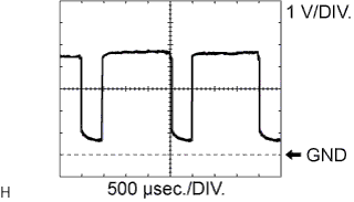
Using an oscilloscope, check waveform 1.
Blower motor control signal Item Content Terminal No. (Symbol) L76-3 (BLW) - L76-1 (GND) Tool Setting 1 V/DIV., 500 μsec./DIV. Condition Power switch ON (IG), Blower switch LO Tech Tips
When the blower level is increased, the duty ratio changes accordingly.
-
Using an oscilloscope, check waveform 2.
Rear blower motor control signal Item Content Terminal No. (Symbol) L76-17 (SBLW) - L76-1 (GND) Tool Setting 1 V/DIV., 500 μsec./DIV. Condition Power switch ON (IG), Blower switch LO Tech Tips
When the rear blower level is increased, the duty ratio changes accordingly.
-
-
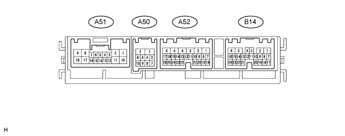
CHECK FRONT CONTROLLER
-
Disconnect the A50, A52 and B14 front controller connectors.
-
Measure the voltage and resistance according to the value(s) in the table below.
Terminal No. (Symbol) Wiring Color Terminal Description Condition Specified Condition B14-14 (SG) - Body ground B - Body ground Ground for pressure sensor Always Below 1 Ω A52-1 (BATB) - A50-2 (E) P - W-B Auxiliary battery power supply Always 11 to 14 V A52-5 (ALTB) - A50-2 (E) L - W-B Auxiliary battery power supply Always 11 to 14 V A50-1 (FMB3) - A50-2 (E) LG - W-B Auxiliary battery power supply Always 11 to 14 V A50-2 (E) - Body ground W-B - Body ground Ground Always Below 1 Ω A50-5 (FMIG) - A50-2 (E) Y - W-B Ignition power supply Power switch ON (IG) 11 to 14 V Power switch OFF Below 1 V -
Reconnect the A50, A52 and B14 front controller connectors.
-
Measure the voltage and resistance according to the value(s) in the table below.
Terminal No. (Symbol) Wiring Color Terminal Description Condition Specified Condition B14-9 (DGSE) - B14-11 (DGS) B - B Exhaust gas sensor signal (CO, HC) 30 seconds after from power switch ON (IG) and the sensor is exposed to the exhaust gas 1.0 to 4.5 V B14-9 (DGSE) - B14-10 (DGS1) B - L Exhaust gas sensor signal (Nox) 30 seconds after from power switch ON (IG) and the sensor is exposed to the exhaust gas 1.0 to 4.5 V B14-12 (S5) - A50-2 (E) B - W-B Power supply for pressure sensor Power switch ON (IG) 4.5 to 5.5 V B14-13 (PRS) - B14-14 (SG) L - B Air conditioning pressure sensor signal Refrigerant pressure: Normal 0.7 to 4.8 V Air conditioning pressure sensor signal Refrigerant pressure: Abnormal (less than 0.196 MPa [2.0 kgf/cm2, 28 psi])
Below 0.7 V Air conditioning pressure sensor signal Refrigerant pressure: Abnormal (more than 3.14 MPa [32 kgf/cm2, 455 psi])
4.8 V or higher B14-14 (SG) - Body ground B - Body ground Ground for pressure sensor Always Below 1 Ω B14-19 (TME) - Body ground L - Body ground Ground for ambient temperature sensor signal Always Below 1 Ω B14-20 (TM) - B14-19 (TME) B - L Ambient temperature sensor signal Power switch ON (IG)
Ambient temperature: 25°C (77°F)
1.8 to 2.2 V Power switch ON (IG)
Ambient temperature: 40°C (105°F)
1.2 to 1.6 V A51-12 (RDEF) - A50-2 (E) W - W-B Rear defogger switch signal Power switch ON (IG)
Rear defogger switch OFF
11 to 14 V Power switch ON (IG)
Rear defogger switch ON
Below 1 V A51-13 (FDEF) - A50-2 (E) L - W-B Window deicer switch signal Power switch ON (IG)
Window deicer switch OFF
11 to 14 V Power switch ON (IG)
Window deicer switch ON
Below 1 V
-
-
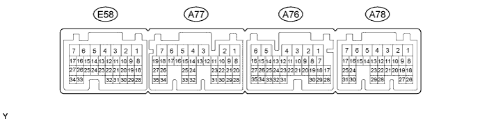
CHECK HYBRID VEHICLE CONTROL ECU
-
Measure the voltage and waveform according to the value(s) in the table below.
Tech Tips
Check from the rear of the connector while it is connected to the hybrid vehicle control ECU.
Terminal No. (Symbol) Wiring Color Terminal Description Condition Specified Condition E58-21 (ITE) - A77-7 (E1) R - W-B Compressor operation signal Power switch ON (READY)
A/C switch OFF
Pulse generation
(see waveform)
E58-30 (CLK) - A77-7 (E1) BR - W-B Compressor operation signal Power switch ON (READY)
A/C switch OFF
Pulse generation
(see waveform)
E58-31 (STB) - A77-7 (E1) L - W-B Compressor operation signal Power switch ON (READY)
A/C switch OFF
Pulse generation
(see waveform)
E58-32 (ETI) - A77-7 (E1) B - W-B Compressor operation signal Power switch ON (READY)
A/C switch OFF
Pulse generation
(see waveform)
A77-5 (WP) - A77-7 (E1) B - W-B Heater water pump operation signal Power switch ON (READY) Below 2 V A76-15 (CANH) Y CAN communication signal - - A76-16 (CANL) L CAN communication signal - - -
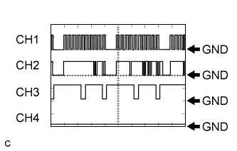
Using an oscilloscope, check waveform.
Compressor operation signal Item Content Terminal No. (Symbol)
-
CH1: E58-21 (ITE) - A77-7 (E1)
-
CH2: E58-30 (CLK) - A77-7 (E1)
-
CH3: E58-31 (STB) - A77-7 (E1)
-
CH4: E58-32 (ETI) - A77-7 (E1)
Tool Setting 10 V/DIV., 100 msec./DIV. Condition Power switch ON (READY)
A/C switch OFF
Tech Tips
The waveform varies depending on the compressor operation signal.
-
-
-
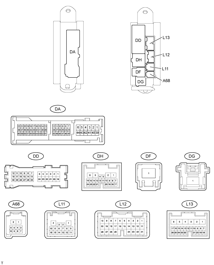
CHECK MAIN BODY ECU (DRIVER SIDE JUNCTION BLOCK)
-
Disconnect the DA, L12 and L13 ECU connectors.
-
Measure the resistance and voltage according to the value(s) in the table below.
Terminal No. (Symbol) Wiring Color Terminal Description Condition Specified Condition DA-40 (GND2) - Body ground W-B - Body ground Ground Always Below 1 Ω L12-1 (AM2) - DA-40 (GND2) W - W-B Auxiliary battery power supply Always 11 to 14 V L13-6 (AM1) - DA-40 (GND2) W - W-B Auxiliary battery power supply Always 11 to 14 V
-
-
CHECK LUGGAGE ROOM JUNCTION BLOCK (REAR JUNCTION BLOCK ECU)

-
Measure the voltage according to the value(s) in the table below.
Tech Tips
Check from the rear of the connector while it is connected to the rear junction block ECU.
Terminal No. (Symbol) Wiring Color Terminal Description Condition Specified Condition S62-5 (RMGV) - LA-43 (PGND) L - W-B Rear magnetic valve operation voltage Power switch ON (IG)
Rear A/C switch ON
Below 1 V Power switch ON (IG)
Rear A/C switch OFF
11 to 14 V S62-7 (SMOK) - LA-43 (PGND)* B - W-B Smoke sensor operation signal Power switch ON (IG)
Rear A/C switch to AUTO
Apply cigarette smoke
4.0 V or higher Power switch ON (IG)
Rear A/C switch to AUTO
No cigarette smoke
Below 1 V S62-18 (TSD) - S62-26 (TSB)* L - B Rear solar sensor signal Power switch ON (IG) 0.8 to 4.3 V Rear solar sensor subjected to electric light S62-25 (RRTE) - LA-51 (SSRE) SB - V Rear evaporator temperature sensor signal Power switch ON (IG)
Rear evaporator temperature: 15°C (59°F)
11 to 14 V
-
*: w/ Rear Cooler
-
-
-
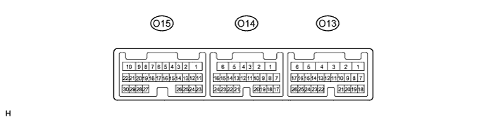
CHECK REAR DOOR ECU LH
-
Disconnect the O14 rear door ECU LH connector.
-
Measure the voltage and resistance according to the value(s) in the table below.
Terminal No. (Symbol) Wiring Color Terminal Description Condition Specified Condition O14-1 (GND) - Body ground W-B - Body ground Ground Always Below 1 Ω O14-6 (BDR) - O14-1 (GND) L - W-B Auxiliary battery power supply Always 11 to 14 V O14-11 (CPUB) - O14-1 (GND) R - W-B Auxiliary battery power supply Always 11 to 14 V -
Reconnect the O14 rear door ECU LH connector.
-
Measure the voltage according to the value(s) in the table below.
Terminal No. (Symbol) Wiring Color Terminal Description Condition Specified Condition O15-13 (TRAD) - O15-26 (TRE) V - Y Rear room temperature sensor signal LH Power switch ON (IG)
Rear LH side interior temperature: 25°C (77°F)
1.8 to 2.2 V
-
-
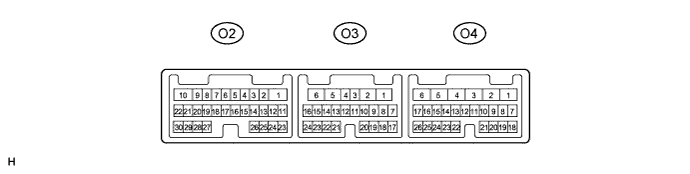
CHECK REAR DOOR ECU RH
-
Disconnect the O3 rear door ECU RH connector.
-
Measure the voltage and resistance according to the value(s) in the table below.
Terminal No. (Symbol) Wiring Color Terminal Description Condition Specified Condition O3-1 (GND) - Body ground W-B - Body ground Ground Always Below 1 Ω O3-6 (BDR) - O3-1 (GND) L - W-B Auxiliary battery power supply Always 11 to 14 V O3-11 (CPUB) - O3-1 (GND) R - W-B Auxiliary battery power supply Always 11 to 14 V -
Reconnect the O3 rear door ECU RH connector.
-
Measure the voltage according to the value(s) in the table below.
Terminal No. (Symbol) Wiring Color Terminal Description Condition Specified Condition O2-13 (TRAD) - O2-26 (TRE) V - Y Rear room temperature sensor signal RH Power switch ON (IG)
Rear RH side interior temperature: 25°C (77°F)
1.8 to 2.2 V
-
-
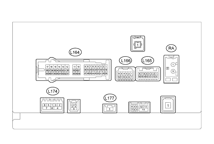
CHECK MULTI-MEDIA MODULE RECEIVER
-
Disconnect the L164 multi-media module receiver connector.
-
Measure the voltage and resistance according to the value(s) in the table below.
Terminal No. (Symbol) Wiring Color Terminal Description Condition Specified Condition L164-12 (GND1) - Body ground W-B - Body ground Ground Always Below 1 Ω L164-17 (+B1) - L164-12 (GND1) R - W-B Auxiliary battery power source Always 11 to 14 V L164-15 (IG) - L164-12 (GND1) V - W-B Ignition power supply Power switch ON (IG) 11 to 14 V Power switch OFF Below 1 V
-
-
CHECK REAR POWER SEAT SWITCH (except for 4-Passenger with Ottoman)

-
Disconnect the z54 rear power seat switch connector.
-
Measure the voltage and resistance according to the value(s) in the table below.
Terminal No. (Symbol) Wiring Color Terminal Description Condition Specified Condition z54-9 (E) - Body ground W-B - Body ground Ground Always Below 1 Ω z54-14 (B) - z54-9 (E) W - W-B Auxiliary battery power source Always 11 to 14 V
-
-
CHECK REAR POWER SEAT SWITCH (for 4-Passenger with Ottoman)

-
Disconnect the S15 rear power seat switch connector.
-
Measure the voltage and resistance according to the value(s) in the table below.
Terminal No. (Symbol) Wiring Color Terminal Description Condition Specified Condition S15-1 (E) - Body ground W-B - Body ground Ground Always Below 1 Ω S15-8 (B) - S15-1 (E) W - W-B Auxiliary battery power source Always 11 to 14 V
-