POWER STEERING ECU INSTALLATION

-
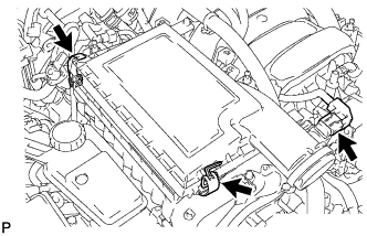
INSTALL POWER STEERING ECU
-
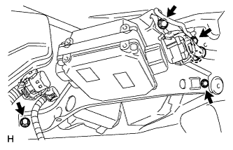
Attach the claw and install the ECU with the 4 bolts.
- Torque:
- 8.5 N*m { 87 kgf*cm, 75 in.*lbf }
-
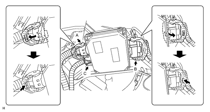
Connect the connector C to the ECU.
-
Connect the ECU connectors A and B and securely lock the connectors.
-
-
INSTALL NO. 1 INVERTER RESERVOIR BRACKET
-
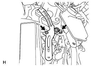
Install the bracket with the 2 bolts.
- Torque:
- 13 N*m { 133 kgf*cm, 10 ft.*lbf }
-
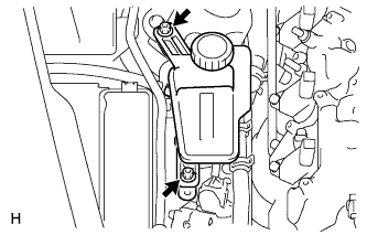
Install the reservoir with the 2 nuts.
- Torque:
- 13 N*m { 133 kgf*cm, 10 ft.*lbf }
-
-
INSTALL AIR CLEANER ASSEMBLY RH
-
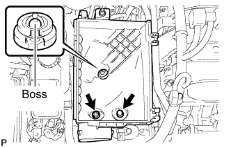
Align the air cleaner cases 2 holes to the 2 stud bolts and attach the air cleaner case RH to the boss. Then install the 2 nuts.
- Torque:
- 5.0 N*m { 51 kgf*cm, 44 in.*lbf }
-
Install the air cleaner filter element to the air cleaner case RH.
-
Install the air cleaner cap RH and secure the 2 clamps.
-
Connect the mass air flow meter connector.
-
-
INSTALL AIR CLEANER INLET COVER SUB-ASSEMBLY
-
Install the inlet cover with the 5 clips.
-
-
INSTALL ENGINE ROOM SIDE COVER
-
Install the engine room side cover RH with the 5 clips.
-
-
CONNECT CABLE TO AUXILIARY BATTERY NEGATIVE TERMINAL
Note
When disconnecting the cable, some systems need to be initialized after the cable is reconnected Click here.
-
INSTALL BATTERY SERVICE HOLE COVER LH
-

Text in Illustration *A for Standard *B for Ottoman Attach the battery service hole cover LH with the clip and fastening tape.
-
-
INSTALL DECK TRIM SIDE BOARD LH (w/o Spare Tire)
-

Attach the 2 clips to install the deck trim side board LH.
-
-
INSTALL DECK BOARD ASSEMBLY (w/o Spare Tire)

-
INSTALL LUGGAGE COMPARTMENT MAT SUB-ASSEMBLY (w/ Spare Tire)

-
PERFORM VARIABLE GEAR RATIO STEERING SYSTEM CALIBRATION