POWER STEERING ECU REMOVAL

-
REMOVE LUGGAGE COMPARTMENT MAT SUB-ASSEMBLY (w/ Spare Tire)

-
REMOVE DECK BOARD ASSEMBLY (w/o Spare Tire)

-
REMOVE DECK TRIM SIDE BOARD LH (w/o Spare Tire)
-

Detach the 2 clips and remove the deck trim side board LH.
-
-
REMOVE BATTERY SERVICE HOLE COVER LH
-

Text in Illustration *A for Standard *B for Ottoman *1 Fastening Tape Detach the clip, fastening tape and remove the battery service hole cover LH.
-
-
PRECAUTION
Note
After turning the power switch off, waiting time may be required before disconnecting the cable from the negative (-) auxiliary battery terminal. Therefore, make sure to read the disconnecting the cable from the negative (-) auxiliary battery terminal notices before proceeding with work Click here.
-
DISCONNECT CABLE FROM AUXILIARY BATTERY NEGATIVE TERMINAL
Note
When disconnecting the cable, some systems need to be initialized after the cable is reconnected Click here.
-
REMOVE ENGINE ROOM COVER SIDE
-
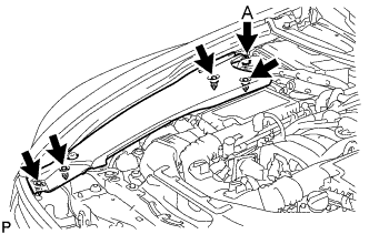
for LHD:
Remove the 5 clips and engine room side cover RH.
Note
Remove the clip labeled A by turning it to prevent the engine room side cover RH and bracket from being damaged.
Tech Tips
The clip labeled A cannot be removed from the engine room side cover RH.
-
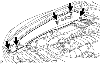
for RHD:
Remove the 5 clips and engine room side cover RH.
-
-
REMOVE AIR CLEANER INLET COVER SUB-ASSEMBLY
-
Remove the 5 clips and inlet cover.
-
-
REMOVE AIR CLEANER ASSEMBLY RH
-
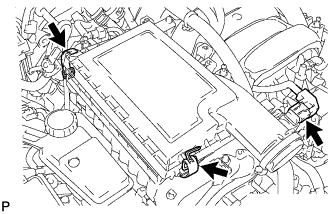
Disconnect the mass air flow meter connector.
-
Release the 2 clamps and remove the air cleaner cap RH.
-
Remove the air cleaner filter element from the air cleaner case RH.
-
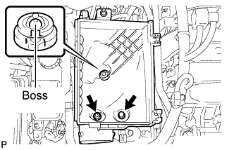
Remove the 2 nuts and detach the air cleaner case RH from the boss.
-
-
REMOVE NO. 1 INVERTER RESERVOIR BRACKET
-
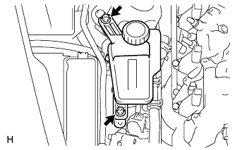
Remove the 2 nuts, and slide the inverter reservoir towards the engine.
-
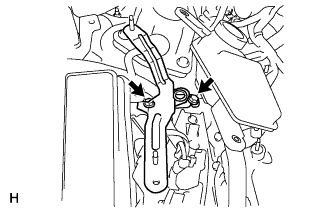
Remove the 2 bolts and bracket.
-
-
REMOVE POWER STEERING ECU
-
Release the locks of ECU connectors A and B and disconnect the connectors.
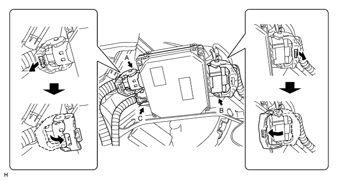
-
Disconnect the connector C from the ECU.
-
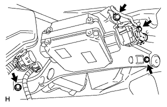
Remove the 4 bolts and detach the claw, and remove the ECU.
-