STEERING GEAR INSTALLATION

-
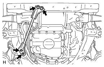
INSTALL POWER STEERING LINK ASSEMBLY
-
Install the power steering link to the front frame with the 2 bolts, 2 washers and 2 nuts.
- Torque:
- 150 N*m { 1530 kgf*cm, 111 ft.*lbf }
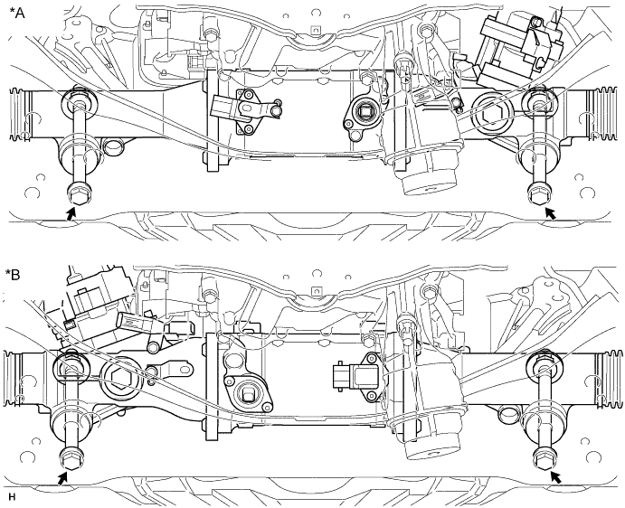
Text in Illustration *A LHD *B RHD -
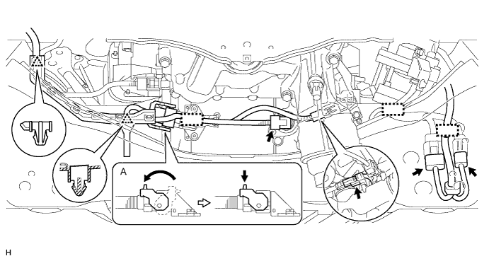
for LHD:
Connect the 5 connectors and attach the 2 clips and 3 clamps.
Tech Tips
Connect connector A as shown in the illustration.
-
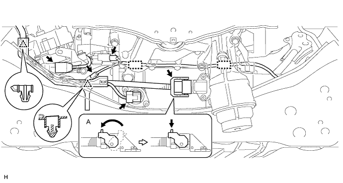
for RHD:
Connect the 5 connectors and attach the 2 clips and 2 clamps.
Tech Tips
Connect connector A as shown in the illustration.
-
-
INSTALL FRONT NO. 1 STABILIZER BAR BUSH
-
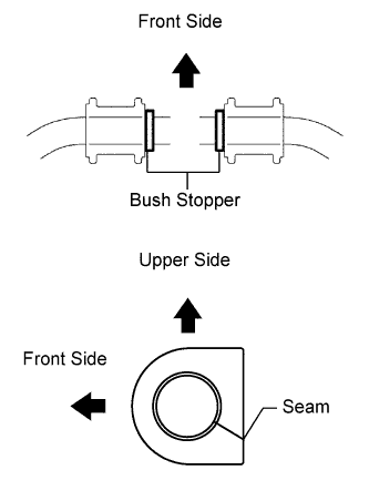
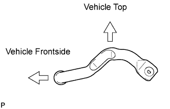
Install the 2 front No. 1 stabilizer bar bushes outside of the bush stoppers on the front stabilizer bar as shown in the illustration.
Note
Make sure to face the front No. 1 stabilizer bar bush's seam to the lower rear of the vehicle.
-
-
INSTALL FRONT STABILIZER BAR
-
Temporarily install the front stabilizer bar and front No. 1 stabilizer bracket LH and RH with the 4 bolts in the direction shown in the illustration.
-
-
INSTALL NO. 1 FRONT STABILIZER BRACKET LH
-
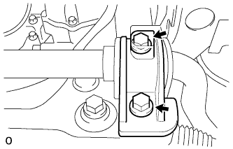
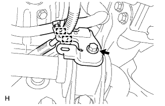
Install the front No. 1 stabilizer bracket LH with the 2 bolts.
- Torque:
- 115 N*m { 1173 kgf*cm, 85 ft.*lbf }
-
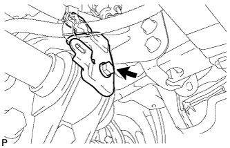
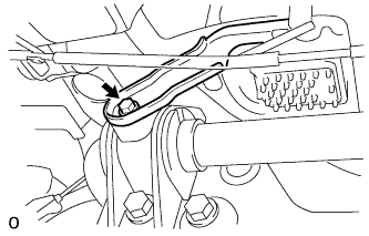
Install the wire harness bracket with the bolt.
- Torque:
- 22 N*m { 224 kgf*cm, 16 ft.*lbf }
-
-
INSTALL NO. 1 FRONT STABILIZER BRACKET RH
-
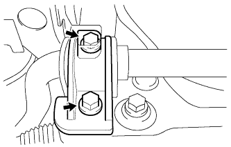
Install the front No. 1 stabilizer bracket RH with the 2 bolts.
- Torque:
- 115 N*m { 1173 kgf*cm, 85 ft.*lbf }
-
Install the water with motor and bracket pump assembly with the bolt.
- Torque:
- 22 N*m { 224 kgf*cm, 16 ft.*lbf }
-
-
INSTALL NO. 2 FRONT STABILIZER BRACKET RH
-
Install the bracket and bolt.
- Torque:
- 22 N*m { 224 kgf*cm, 16 ft.*lbf }
-
Connect the 2 clamps.
-
-
CONNECT TIE ROD ASSEMBLY LH
-
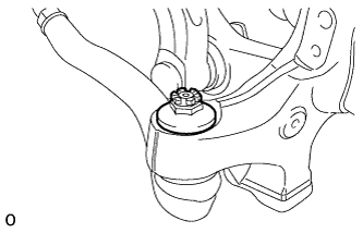
Connect the tie rod to the steering knuckle with the nut.
- Torque:
- 60 N*m { 612 kgf*cm, 44 ft.*lbf }
-
Install new clips.
Note
If it is necessary to align the holes for the clips after installing the nuts, the nuts can be tightened up to 60° more.
-
-
CONNECT TIE ROD ASSEMBLY RH
Tech Tips
Use the same procedures described for the LH side.
-
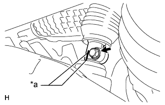
CONNECT NO. 2 STEERING INTERMEDIATE SHAFT ASSEMBLY
-
Install the clamp to the steering column hole cover sub-assembly.
-
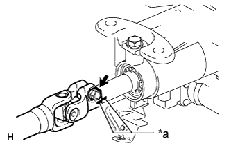
Text in Illustration *a Matchmark Align the matchmarks on the No. 2 steering intermediate shaft assembly and steering column.
-
Install the bolt.
- Torque:
- 35 N*m { 360 kgf*cm, 26 ft.*lbf }
-
Text in Illustration *a Matchmark Align the matchmarks on the No. 2 steering intermediate shaft assembly and power steering link.
-
Install the bolt.
- Torque:
- 35 N*m { 360 kgf*cm, 26 ft.*lbf }
-
-
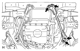
INSTALL FRONT SUSPENSION MEMBER BRACKET SUB-ASSEMBLY RH
-
Install the front bracket with the 4 bolts.
- Torque:
- 59 N*m { 603 kgf*cm, 44 ft.*lbf }
-
-
INSTALL FRONT SUSPENSION MEMBER BRACKET SUB-ASSEMBLY LH
-
Install the front suspension member bracket with the 4 bolts.
- Torque:
- 59 N*m { 603 kgf*cm, 44 ft.*lbf }
-
-
INSTALL FRONT LOWER SUSPENSION MEMBER PROTECTOR
-

Install the front lower suspension member protector with the 9 bolts.
- Torque:
- for bolt A
- 20 N*m { 204 kgf*cm, 15 ft.*lbf }
- except bolt A
- 58 N*m { 593 kgf*cm, 43 ft.*lbf }
-
-
INSTALL NO. 2 ENGINE UNDER COVER
-
Install the No. 2 engine under cover with the 4 screws and 2 clips.
-
-
INSTALL NO. 1 ENGINE UNDER COVER
-
Install the No. 1 engine under cover with the 13 screws and 7 clips.
-
-
INSTALL FRONT WHEELS
- Torque:
- 140 N*m { 1428 kgf*cm, 103 ft.*lbf }
-
PLACE FRONT WHEELS FACING STRAIGHT AHEAD
-
CONNECT CABLE TO AUXILIARY BATTERY NEGATIVE TERMINAL
Note
When disconnecting the cable, some systems need to be initialized after the cable is reconnected Click here
-
INSTALL BATTERY SERVICE HOLE COVER LH
-
INSTALL DECK TRIM SIDE BOARD LH (w/o Spare Tire)
-

Attach the 2 clips to install the deck trim side board LH.
-
-
INSTALL DECK BOARD ASSEMBLY (w/o Spare Tire)

-
INSTALL LUGGAGE COMPARTMENT MAT SUB-ASSEMBLY (w/ Spare Tire)

-
CHECK SUSPENSION CONTROL SYSTEM
-
INSPECT AND ADJUST FRONT WHEEL ALIGNMENT
-
ADJUST HEADLIGHT AIMING
-
ADJUST OBJECT RECOGNITION CAMERA
-
INITIALIZE ROTATION ANGLE SENSOR AND CALIBRATE TORQUE SENSOR ZERO POINT
-
PERFORM VARIABLE GEAR RATIO STEERING SYSTEM CALIBRATION