STEERING GEAR REMOVAL

-
PLACE FRONT WHEELS FACING STRAIGHT AHEAD
-
REMOVE LUGGAGE COMPARTMENT MAT SUB-ASSEMBLY (w/ Spare Tire)

-
REMOVE DECK BOARD ASSEMBLY (w/o Spare Tire)

-
REMOVE DECK TRIM SIDE BOARD LH (w/o Spare Tire)
-

Detach the 2 clips and remove the deck trim side board LH.
-
-
REMOVE BATTERY SERVICE HOLE COVER LH
-

Text in Illustration *A for Standard *B for Ottoman *1 Fastening Tape Detach the clip, fastening tape and remove the battery service hole cover LH.
-
-
PRECAUTION
Note
After turning the power switch off, waiting time may be required before disconnecting the cable from the negative (-) auxiliary battery terminal. Therefore, make sure to read the disconnecting the cable from the negative (-) auxiliary battery terminal notices before proceeding with work Click here.
-
DISCONNECT CABLE FROM AUXILIARY BATTERY NEGATIVE TERMINAL
CAUTION:
Wait at least 90 seconds after disconnecting the cable from the negative (-) auxiliary battery terminal to prevent airbag and seat belt pretensioner activation.
Note
When disconnecting the cable, some systems need to be initialized after the cable is reconnected Click here.
-
REMOVE FRONT WHEELS
-
REMOVE NO. 1 ENGINE UNDER COVER
-
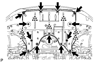
Remove the 13 screws, 7 clips and No. 1 engine under cover.
-
-
REMOVE NO. 2 ENGINE UNDER COVER
-
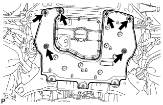
Remove the 4 screws, 2 clips and No. 2 engine under cover.
-
-
REMOVE FRONT LOWER SUSPENSION MEMBER PROTECTOR
-
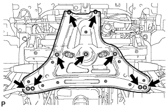
Remove the 9 bolts and front lower suspension member protector.
-
-
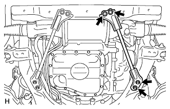
REMOVE FRONT SUSPENSION MEMBER BRACKET SUB-ASSEMBLY LH
-
Remove the 4 bolts and bracket.
-
-
REMOVE FRONT SUSPENSION MEMBER BRACKET SUB-ASSEMBLY RH
-
Remove the 4 bolts and bracket.
-
-
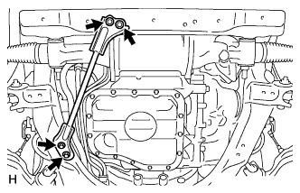
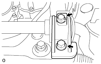
DISCONNECT NO. 2 STEERING INTERMEDIATE SHAFT ASSEMBLY
-
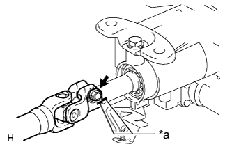
Text in Illustration *a Matchmark Put matchmarks on the No. 2 steering intermediate shaft and the steering column.
-
Remove the bolt.
-
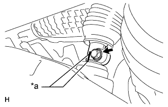
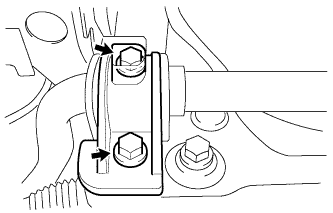
Text in Illustration *a Matchmark Put matchmarks on the No. 2 steering intermediate shaft and the steering link.
-
Remove the bolt.
-
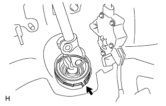
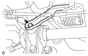
Remove the clamp and No. 2 steering intermediate shaft.
-
-
DISCONNECT TIE ROD ASSEMBLY LH
-
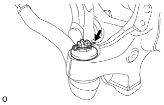
Remove the clip and nut.
-
Install 2 spacers (SST spacer B) onto the tie rod assembly LH so that there is a space of approximately 1 mm (0.0394 in.) between the arm and spacers.
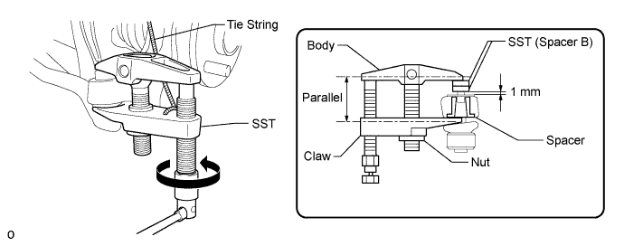
- SST
- 09960-20010 ( 09961-02060 )
Note
-
Make sure to install the spacers (SST spacer B) as the steering knuckle spacer may shift.
-
As SST may become damaged, make sure the space between the arm and spacers is not less than 1 mm (0.0394 in.).
-
Using SST, disconnect the tie rod assembly from the steering knuckle.
- SST
- 09960-20010 ( 09961-02010 )
Note
-
Apply molybdenum grease to the threads and end of the SST bolt.
-
Do not damage the dust cover.
-
As the dust cover may be damaged, adjust SST with the center nut so that the body and claw are the parallel.
-
Make sure to tie the string of SST to the vehicle to prevent SST from dropping.
-
-
DISCONNECT TIE ROD ASSEMBLY RH
Tech Tips
Use the same procedures described for the LH side.
-
REMOVE NO. 2 FRONT STABILIZER BRACKET RH
-
Disconnect the 2 clamps.
-
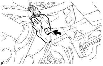
Remove the bolt and bracket.
-
-
REMOVE FRONT NO. 1 STABILIZER BRACKET LH
-
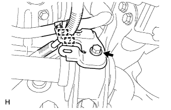
Remove the bolt and wire harness bracket.
-
Remove the 2 bolts and front No. 1 stabilizer bracket LH from the front frame assembly.
-
-
REMOVE FRONT NO. 1 STABILIZER BRACKET RH
-
Remove the bolt and disconnect the water with motor and bracket pump bracket.
-
Remove the 2 bolts and the front No. 1 stabilizer bracket RH from the front frame assembly.
-
-
REMOVE STABILIZER BAR FRONT
-
Remove the front stabilizer bar from the vehicle.
-
-
REMOVE FRONT NO. 1 STABILIZER BAR BUSH
-
Remove the 2 front No. 1 stabilizer bar bushes from the front stabilizer bar.
-
-
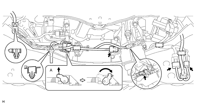
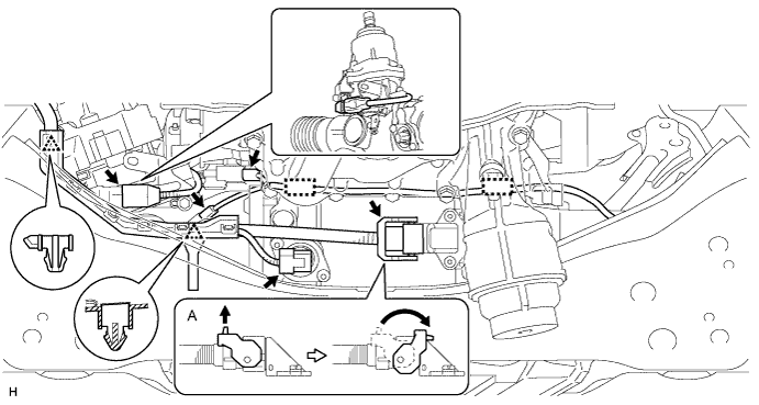
REMOVE POWER STEERING LINK ASSEMBLY
-
for LHD:
Detach the 2 clips, 3 clamps and disconnect the 5 connectors.
Tech Tips
Disconnect connector the A as shown in the illustration.
-
for RHD:
Detach the 2 clips, 2 clamps and disconnect the 5 connectors.
Tech Tips
Disconnect connector the A as shown in the illustration.
-
Remove the 2 bolts, 2 nuts, 2 washers and power steering link from the front frame.
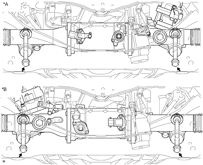
Text in Illustration *A for LHD *B for RHD
-