AIR CONDITIONING SYSTEM, Diagnostic DTC:B1415/15

| DTC Code | DTC Name |
|---|---|
| B1415/15 | Driver Side Duct Sensor |
DESCRIPTION
The air duct sensor (for driver side) detects the register temperature and sends the appropriate signals to the air conditioning amplifier.
| DTC Code | Detection item | Trouble Area |
|---|---|---|
| B1415/15 | Air duct sensor circuit (for driver side) (Open or short) |
|
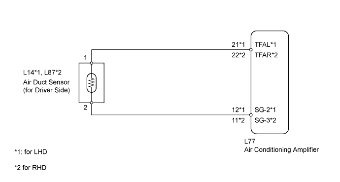
WIRING DIAGRAM
INSPECTION PROCEDURE
PROCEDURE
-
READ VALUE USING INTELLIGENT TESTER (DUCT SENSOR (for Driver Side))
-
Use the Data List to check if the duct sensor (for driver side) is functioning properly.
Air conditioner Tester Display Measure Item / Range Normal Condition Diagnostic Note Duct Sensor (D Side) Duct sensor (for driver side) /
Min.: -12.7°C (9.14°F)
Max.: 76.55°C (169.79°F)
Actual duct temperature is displayed (for driver side) - OK The display is as specified in the normal condition.
NG 
CHECK AIR CONDITIONING AMPLIFIER (TFAL - SG-2, TFAR-SG-3 VOLTAGE) Click here
OK 
REPLACE AIR CONDITIONING AMPLIFIER Click here
-
-
CHECK AIR CONDITIONING AMPLIFIER (TFAL - SG-2, TFAR-SG-3 VOLTAGE)
-
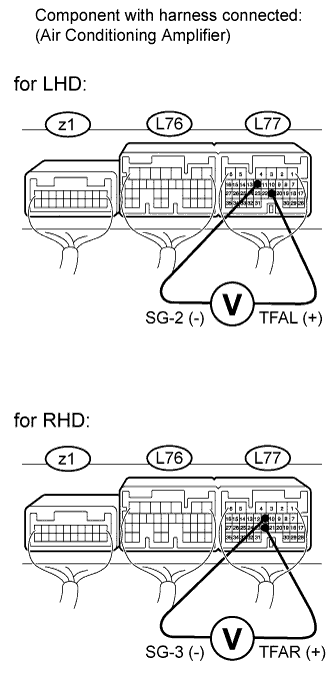
Remove the air conditioning amplifier with its connectors still connected Click here.
-
Measure the voltage according to the value(s) in the table below.
Standard voltage for LHD Tester Connection Condition Specified Condition L77-21 (TFAL) - L77-12 (SG-2) Power switch ON (IG) at 25°C (77°F) 1.8 to 2.2 V Power switch ON (IG) at 50°C (122°F) 0.8 to 1.2 V for RHD Tester Connection Condition Specified Condition L77-22 (TFAR) - L77-11 (SG-3) Power switch ON (IG) at 25°C (77°F) 1.8 to 2.2 V Power switch ON (IG) at 50°C (122°F) 0.8 to 1.2 V Tech Tips
As the temperature increases, the voltage decreases.
NG
CHECK AIR DUCT SENSOR Click here
OK
REPLACE AIR CONDITIONING AMPLIFIER Click here
-
-
CHECK AIR DUCT SENSOR
-
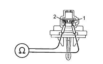
Remove the air duct sensor Click here.
-
Measure the resistance according to the value(s) in the table below.
Standard resistance Tester Connection Condition Specified Condition 1 - 2 0°C (32°F) 14.5 to 19.0 kΩ 25°C (77°F) 4.8 to 5.2 kΩ 50°C (122°F) 1.6 to 2.0 kΩ Tech Tips
As the temperature increases, the resistance decreases.
NG 
REPLACE AIR DUCT SENSOR Click here
OK 
-
-
CHECK HARNESS AND CONNECTOR (AIR CONDITIONING AMPLIFIER - AIR DUCT SENSOR)
-
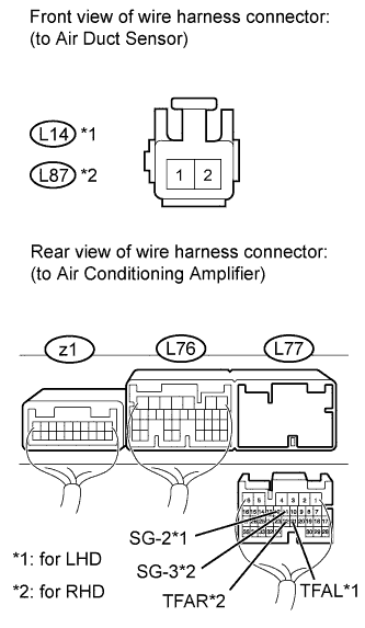
Disconnect the L14*1 or L87*2 air duct sensor connector.
-
Disconnect the L77 air conditioning amplifier connector.
-
Measure the resistance according to the value(s) in the table below.
Standard resistance for LHD Tester Connection Condition Specified Condition L77-21 (TFAL) - L14-1 Always Below 1 Ω L77-12 (SG-2) - L14-2 L77-21 (TFAL) - Body ground Always 10 kΩ or higher L77-12 (SG-2) - Body ground for RHD Tester Connection Condition Specified Condition L77-22 (TFAR) - L87-1 Always Below 1 Ω L77-11 (SG-3) - L87-2 L77-22 (TFAR) - Body ground Always 10 kΩ or higher L77-11 (SG-3) - Body ground
NG
REPAIR OR REPLACE HARNESS OR CONNECTOR
OK
REPLACE AIR CONDITIONING AMPLIFIER Click here
-